
Chinese Journal of Catalysis ›› 2026, Vol. 90: 298-308.DOI: 10.1016/S1872-2067(26)65156-X
• Articles • Previous Articles Next Articles
Fang Lia,b, Chen Guana, Zhihan Yua, Quanjun Xianga,*( )
)
Received:2026-01-23
Accepted:2026-03-06
Online:2026-11-05
Published:2026-09-09
About author:First author contact: Fang Li conceived the idea, designed the experiments, and finished the original draft. Chen Guan performed the theoretical calculations. Zhihan Yu designed figures and reviewed the manuscript. Quanjun Xiang supervised the work, reviewed and edited the manuscript.
Supported by:Fang Li, Chen Guan, Zhihan Yu, Quanjun Xiang. Revealing the mechanism of asymmetric charge carrier extraction[J]. Chinese Journal of Catalysis, 2026, 90: 298-308.
Add to citation manager EndNote|Ris|BibTeX
URL: https://www.cjcatal.com/EN/10.1016/S1872-2067(26)65156-X
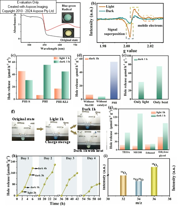
Fig. 1. Origin and dynamic tracking of charge transfer. (a) DRS spectra of excited state (blue-green radical) and original state of PHI slurried with TEOA. The excited state of PHI sample was obtained by nitrogen purging for 5 min and Xenon lamp illumination for 10 min. (b) In-situ EPR spectroscopy of PHI dispersed in methanol solution under nitrogen purge. (c) Hole generation performance of PHI, PHI-S, and PHI-KLi samples in the light and dark-states (hole quantification is converted from O2 yield). Unless otherwise specified in the performance tests, methanol sacrificial agents were added. (d) Dark-state hole-generating activity of PHI without hole scavenger or catalyst. (e) Dark-state hole-generating activity of PHI under light-only and heat-only conditions. Here heat-only conditions are defined as three-necked flasks containing the samples being heated under a water bath at 80 °C for 1 h. (f) Apparent color change of PHI during charge storage and release. (g) Hole generation performance of PHI in light and dark-states under different hole scavenger conditions. Here, dark-state hole yields were obtained after heating for 1 h at 80 °C. (h) Cycling experiments on the release of holes from PHI. (i) Isotope tracking experiment labeled with H218O during O2 evolution among PHI.
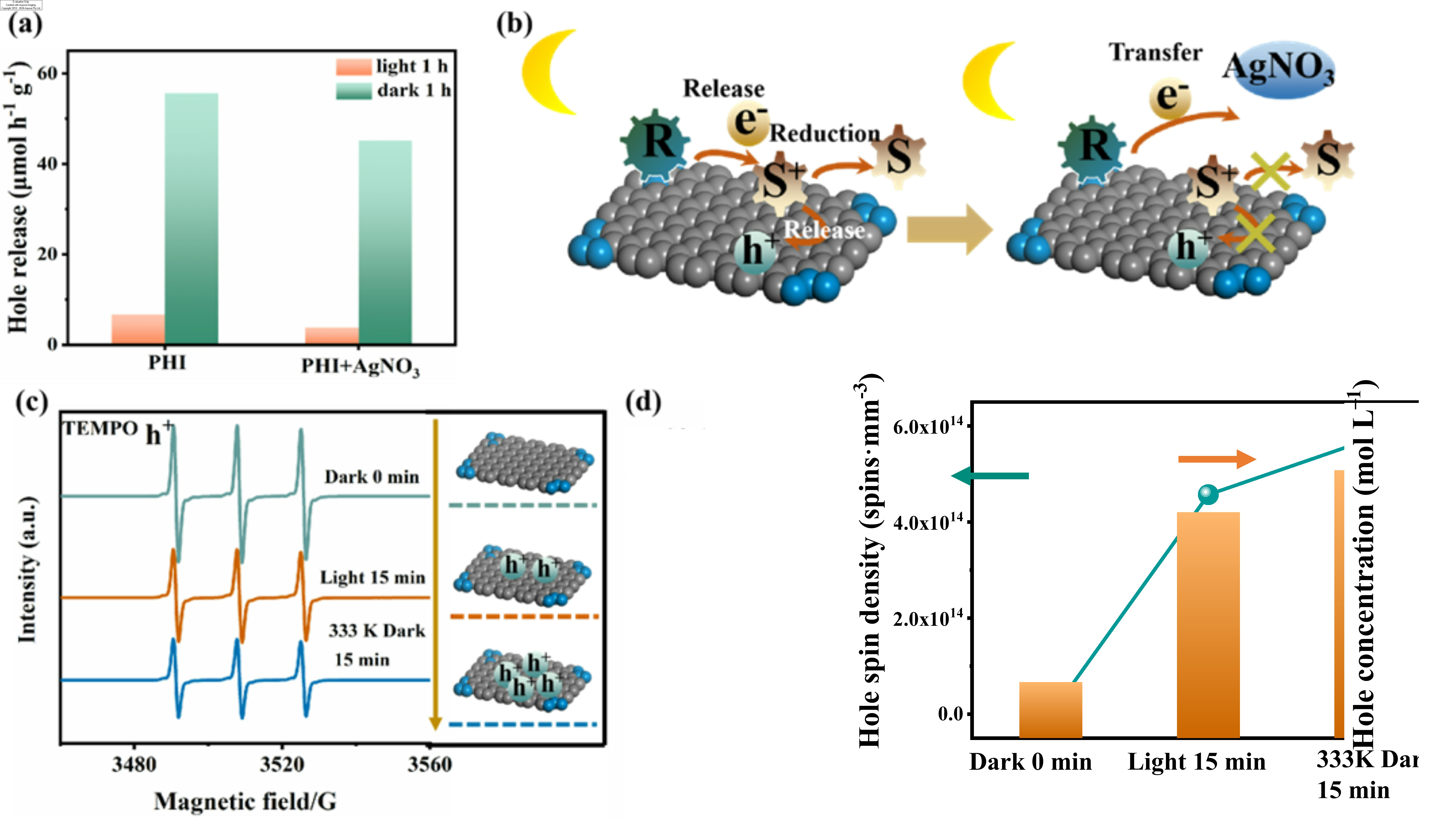
Fig. 2. Mechanism verification of charge storage induced hole catalysis. (a) Hole release activity of the PHI sample before and after the addition of electron scavenger under light and dark conditions. (b) Schematic of hole transfer path in the presence of electron scavenger. When no electron scavenger is added, the electrons captured by free radicals are slowly released in the dark-state and the oxidized hole scavenger is reduced, inducing hole release. After adding electron scavenger, the released electrons are quenched by AgNO3, inhibiting the hole release process. Hole species capture experiment (c) and quantification (d) of hole concentration.
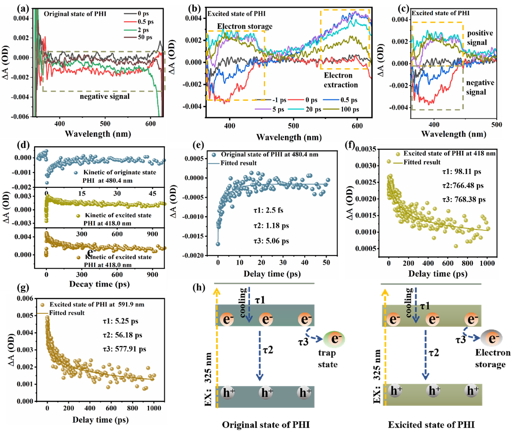
Fig. 3. Asymmetric carrier extraction kinetics. (a) Femtosecond transient absorption spectrum of PHI in its original state. The sample is dispersed in an acetonitrile solution. (b,c) Femtosecond transient absorption spectrum of PHI in its excited state. The sample is dispersed in a methanol solution and purged with nitrogen for 15 min prior to testing. (d) Decay kinetics of PHI in the original and excited states. (e) Kinetic decay plot of PHI in the original-state at 480.4 nm. Kinetic decay plot of PHI in the excited-state at 418 nm (f) and at 591.9 nm (g). (h) Mechanism of asymmetric charge carrier extraction.
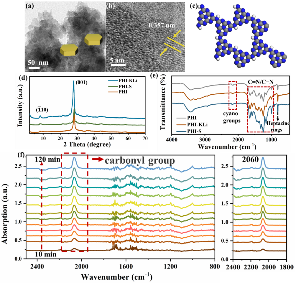
Fig. 4. Structural analysis of the causes of asymmetric charge extraction. (a) TEM image of PHI. The crystal growth of PHI is shown in the lower right of the figure. (b) HRTEM image of PHI. (c) Crystal structure of PHI. (d) XRD patterns of PHI, PHI-S, and PHI-KLi. (e) FTIR spectra of PHI, PHI-S, and PHI-KLi. (f) In-situ DRIFTS of the structural changes of the PHI sample under illumination in a nitrogen and water vapor atmosphere.
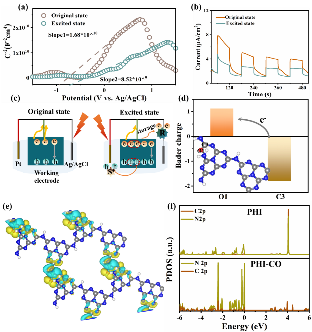
Fig. 5. Further extensions of the asymmetric charge extraction phenomenon. Mott-Schottky curves (a) and photocurrent curves (b) of PHI samples in excited and original state. The voltage applied in the photocurrent test was 0.5 V. (c) Schematic of electro-chemical tests of the sample in excited and original state. Compared to the original state, the free electron density of the sample is higher in the excited state, and the sample exhibits a significant charge storage behavior in the excited state. (d) The Barder charge distribution between O1 and C3 in PHI-CO (PHI-CO was used to simulate the structure of the PHI sample in the excited state). The inset shows the structural unit of PHI-CO. (e) Differential charge density of PHI-CO. The isosurface level is 1.28 × 10⁻³ e/bohr3. (f) PDOS plots of PHI and PHI-CO.
|
| No related articles found! |
| Viewed | ||||||
|
Full text |
|
|||||
|
Abstract |
|
|||||


