
催化学报 ›› 2026, Vol. 89: 142-176.DOI: 10.1016/S1872-2067(26)65055-3
郭姿显a, 何有杭a, 于明飞a, 李留义a,*( ), 毕进红b,*(), 于岩a, 吴棱c,*()
收稿日期:2026-02-01
接受日期:2026-02-27
出版日期:2026-10-18
发布日期:2026-09-01
通讯作者:
*电子信箱: lyli@fzu.edu.cn (李留义),基金资助:
Zixian Guoa, Youhang Hea, Mingfei Yua, Liuyi Lia,*(), Jinhong Bib,*(), Yan Yua, Ling Wuc,*()
Received:2026-02-01
Accepted:2026-02-27
Online:2026-10-18
Published:2026-09-01
Contact:
*E-mail:lyli@fzu.edu.cn(L. Li),bijinhong@fzu.edu.cn(J. Bi),wuling@fzu.edu.cn(L. Wu).
About author:Liuyi Li (College of Materials Science and Engineering, Fuzhou University) received his M.S. degree in Organic Chemistry from Huazhong University of Science and Technology in 2007 and his Ph.D. degree in Environmental Chemistry from Fuzhou University in 2017. He has been working at Fuzhou University since 2017, and was promoted to a full professor in 2021. His research interests currently focus on the rational design of covalent organic frameworks for photocatalysis, with emphasis on CO2 reduction and water splittingSupported by:摘要:
面对日益严峻的能源危机与环境挑战, 太阳能驱动的光催化转化已成为实现可持续发展的关键技术路径之一. 共价有机框架材料凭借其结构可调性、高结晶度及有序孔道等优势, 为突破传统无机半导体材料在分子水平上难以精准调控的瓶颈提供了全新平台. 然而, 当前基于COF粉末的光催化体系仍受制于光生载流子复合率高、光响应范围窄等局限, 同时, 在宏观应用中面临催化剂回收困难、易团聚失活、难以集成于连续流反应系统等工程难题, 严重阻碍了其从基础研究向实际应用的转化. 因此, 开发兼具高效电荷分离能力与宏观可操作性的新型COF光催化体系, 具有重要的科学意义和应用价值.
本文系统阐述了一种从分子到宏观尺度的跨尺度工程策略, 旨在通过协同纳米尺度的异质结设计与宏观尺度的膜结构工程, 以破解上述瓶颈. 首先, 从分子工程视角出发, 系统梳理了COF基异质结的设计思路与优势, 总结了将COF与无机半导体、金属及量子点等材料复合的多样化策略, 重点分析了S型异质结在促进空间电荷分离、保持强氧化还原能力方面的独特机制, 并归纳了决定其光催化性能提升的构效关系, 揭示了界面相互作用对载流子迁移路径的关键影响. 其次, 从宏观结构工程层面, 详细评述了COF膜的制备技术(如界面聚合法、原位生长法、层层堆叠法), 阐明了通过调控膜厚、孔道取向、孔隙率及表面润湿性等参数优化光吸收、反应物富集与传质效率的机制, 进而构建高效的宏观反应界面. 在此基础上, 前瞻性地提出并重点阐述了COF异质结膜这一集成平台: 在纳米尺度上, 利用界面内建电场显著加速载流子动力学, 有效抑制体相复合; 在宏观尺度上, 借助膜结构实现催化剂固定化与连续流操作, 大幅提升催化剂的运行稳定性和可回收性. 二者的协同作用不仅实现了光生电荷的空间分离, 同时优化了反应物在孔道内的扩散行为, 展现出显著的增效机制. 得益于异质结界面的高效电荷分离与膜结构提供的快速传质通道, 所构建的COF异质结膜在光催化产氢、污染物降解等应用中表现出优异的性能提升.
综上, 本文系统梳理了COF光催化剂从分子设计到宏观组装的跨尺度研究, 揭示了异质结与膜结构的协同集成是突破粉末体系应用瓶颈的关键路径. 未来研究应聚焦于规模化制备技术、应用导向的材料设计, 以及系统集成与可持续性评估. 本文旨在为开发兼具高本征活性与工程适用性的新型COF光催化体系提供理论借鉴, 推动光催化技术的实用化进程.
郭姿显, 何有杭, 于明飞, 李留义, 毕进红, 于岩, 吴棱. 面向实用光催化的共价有机框架多尺度工程:从异质结结构设计到膜制备[J]. 催化学报, 2026, 89: 142-176.
Zixian Guo, Youhang He, Mingfei Yu, Liuyi Li, Jinhong Bi, Yan Yu, Ling Wu. Multiscale engineering of COFs toward practical photocatalysis: From heterojunction design to membrane fabrication[J]. Chinese Journal of Catalysis, 2026, 89: 142-176.
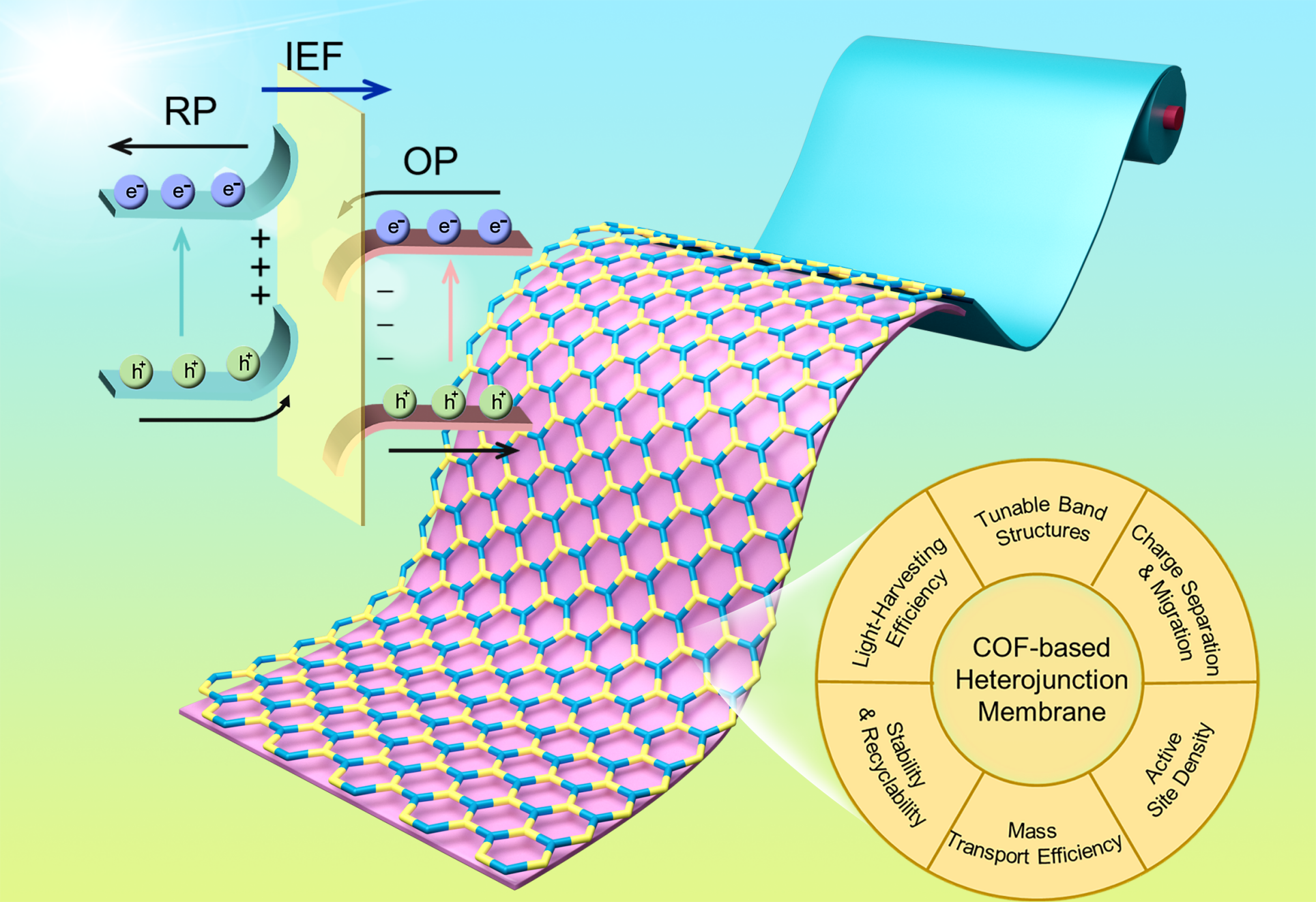
Fig. 1. Schematic representation of COF-based heterojunction membranes for photocatalysis.
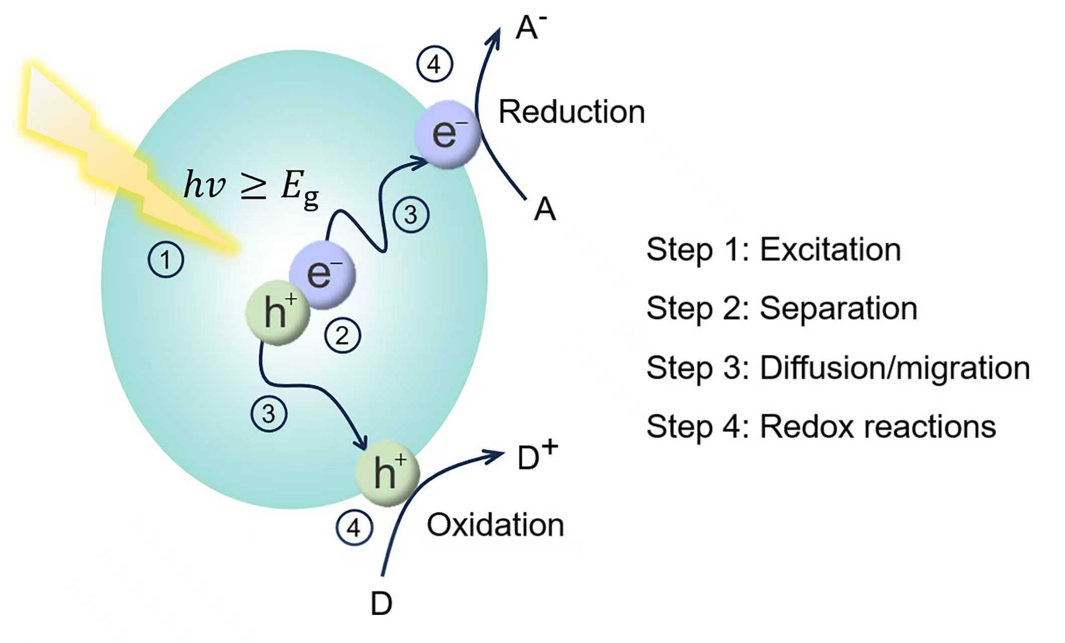
Fig. 2. Reaction mechanism of semiconductor photocatalysis.
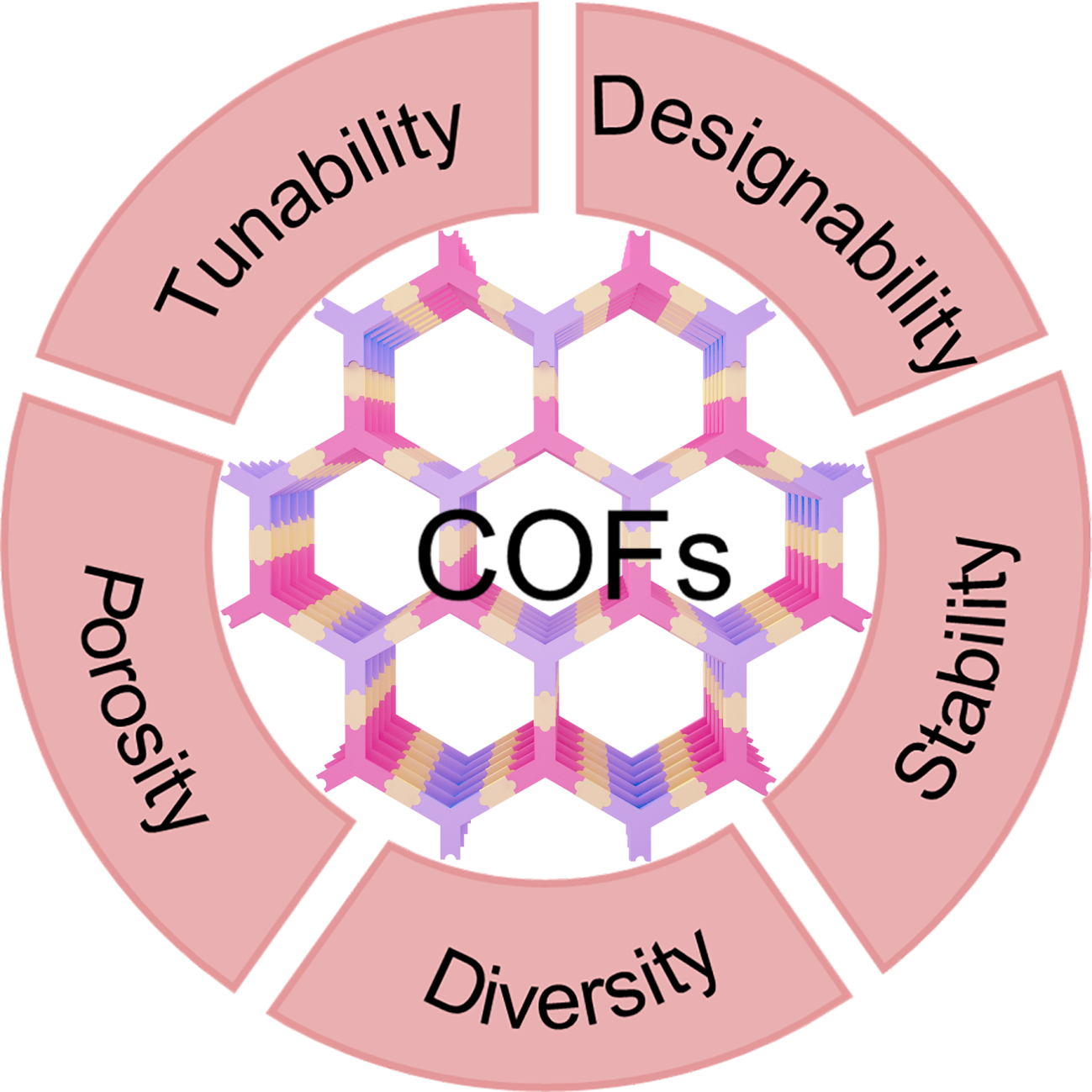
Fig. 3. Advantages of COFs as photocatalysts.
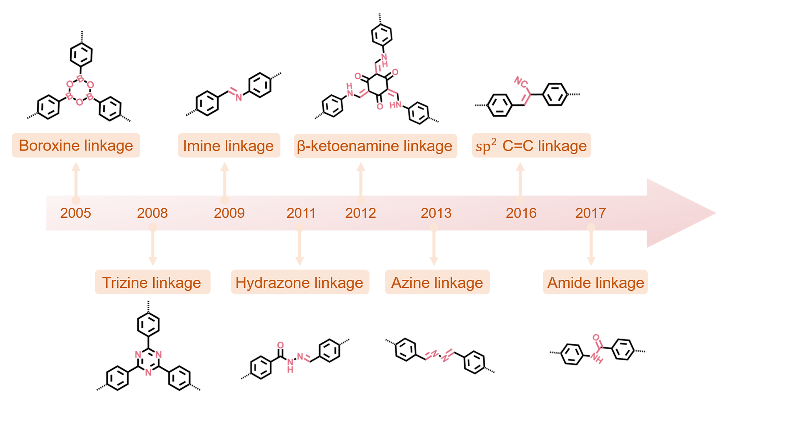
Fig. 4. Timeline of major linkages in photoactive covalent organic framework synthesis. The amide linkage is a representative stable motif.
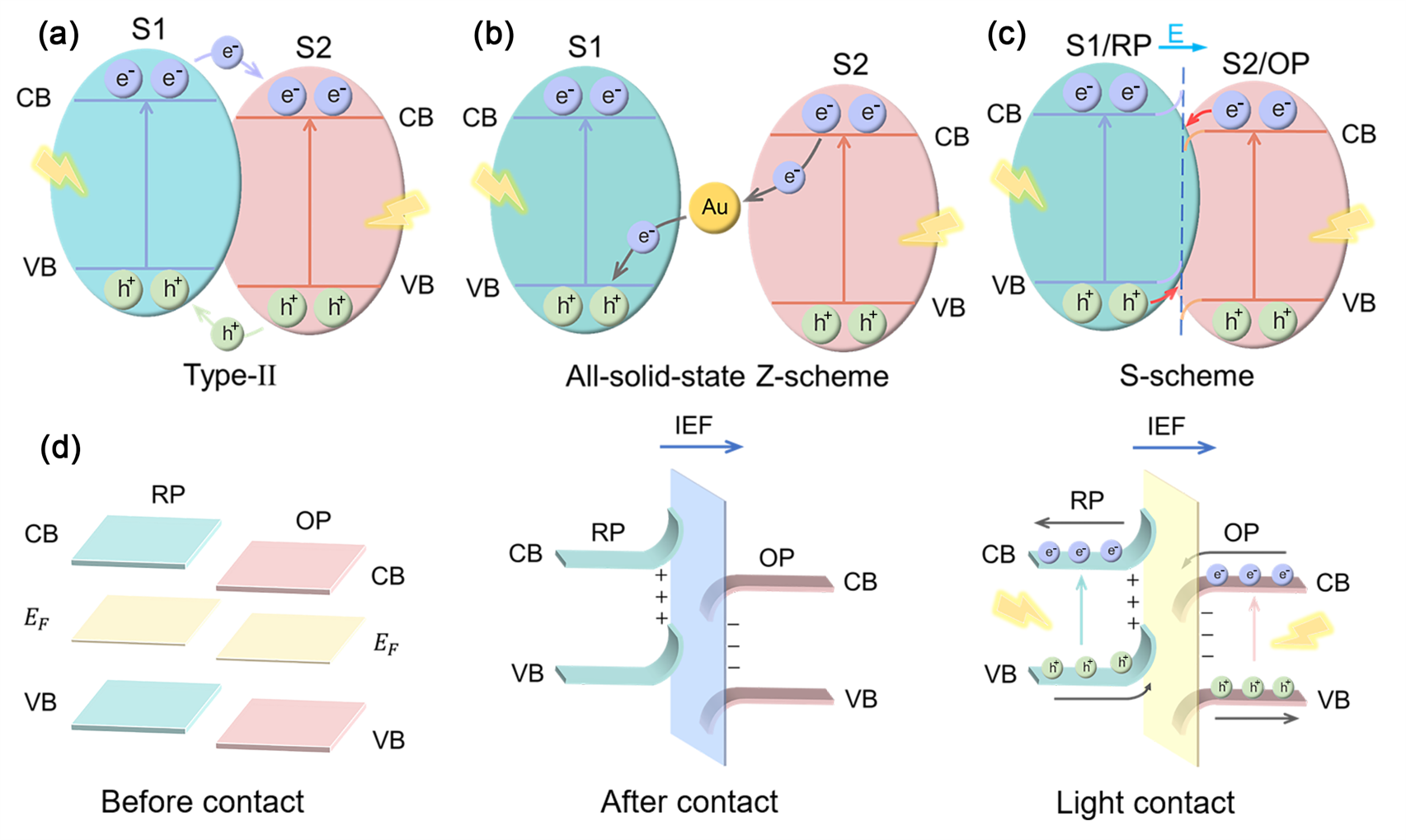
Fig. 5. (a) Type-II heterojunction. (b) Z-scheme heterojunction. (c) S-scheme heterojunction. (d) Charge transfer processes in S-scheme heterojunction.
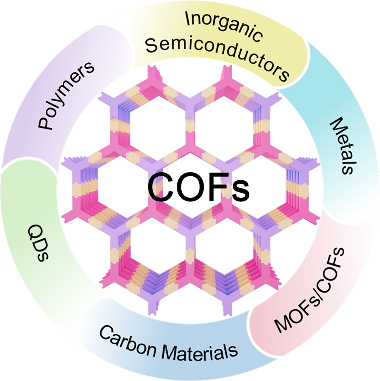
Fig. 6. Fabrication of COF-based photocatalysts via combination with different materials.
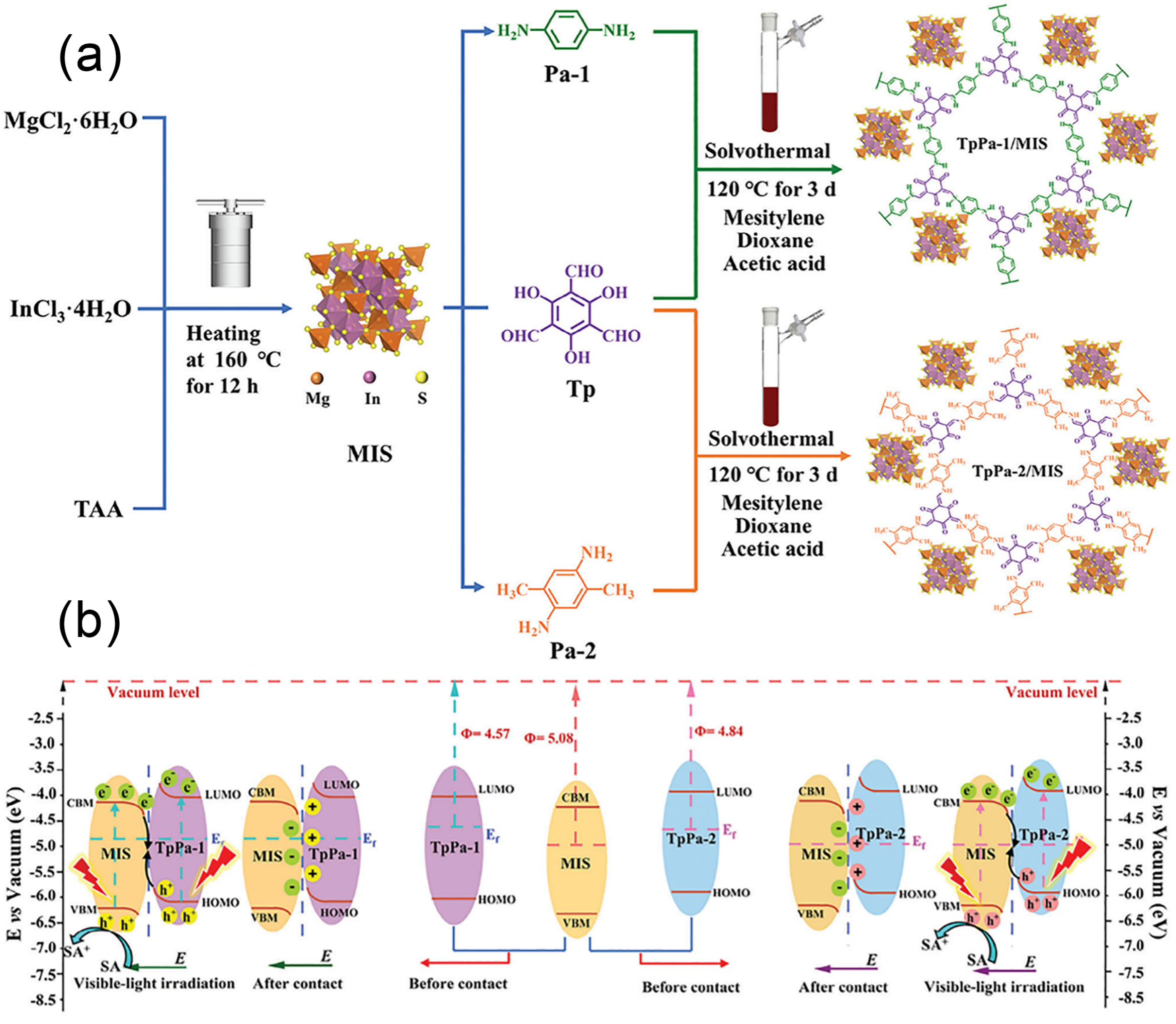
Fig. 7. (a) Schematic illustration of the TpPa-1/MIS and TpPa-2/MIS heterojunction preparation. (b) S-scheme charge migration in TpPa/MIS heterojunctions. Reprinted with permission from Ref. [69]. Copyright 2025, John Wiley and Sons.

Fig. 8. (a) Schematic of the synthesis for PtNPs@CTF-1. (b) TEM image of PtNPs@CTF-1 (scale bar: 10 nm) showing the lattice fringes of PtNPs. (c) The reaction mechanism for PtNPs@CTF-1. Reprinted with permission from Ref. [70]. Copyright 2024, Springer Nature. (d) Proposed photocatalytic CO2-to-CO mechanism over Fe SAS/Tr-COFs. (e) Top-view charge density difference of Fe SAS/Tr-COFs. Skyblue, electron accumulation; yellow, depletion. Reprinted with permission from Ref. [74]. Copyright 2022, American Chemical Society.
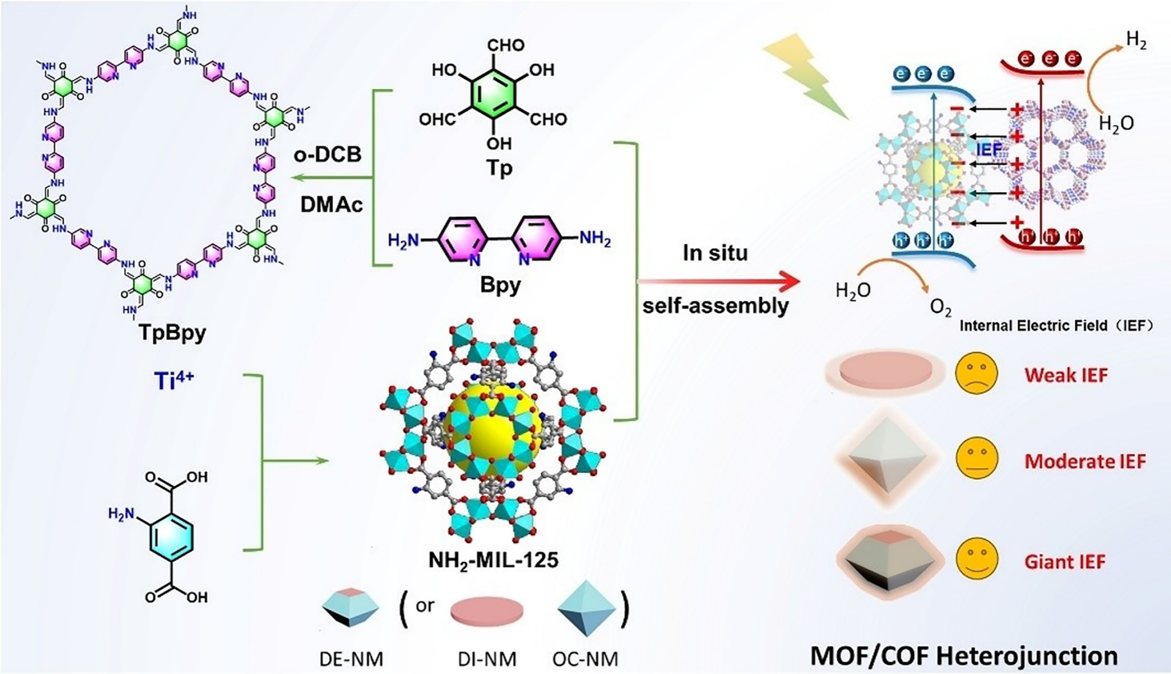
Fig. 9. Schematic of the synthesis for the NH2-MIL-125(Ti)/TpBpy-COF hybrid material. Reprinted with permission from Ref. [79]. Copyright 2025, John Wiley and Sons.
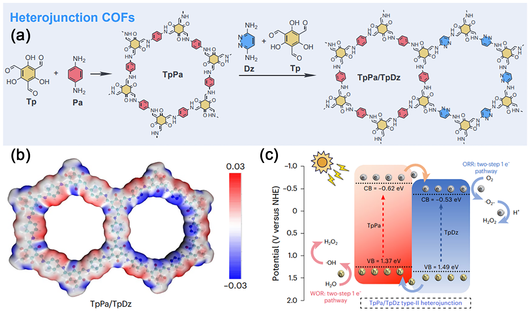
Fig. 10. (a) Structure and Synthesis of the TpPa/TpDz Heterojunction. (b) Electrostatic potential surfaces (EPSs) of TpPa/TpDz. (c) Mechanism for H2O2 photoproduction on the TpPa/TpDz heterojunction. Reprinted with permission from Ref. [82]. Copyright 2025, Springer Nature.
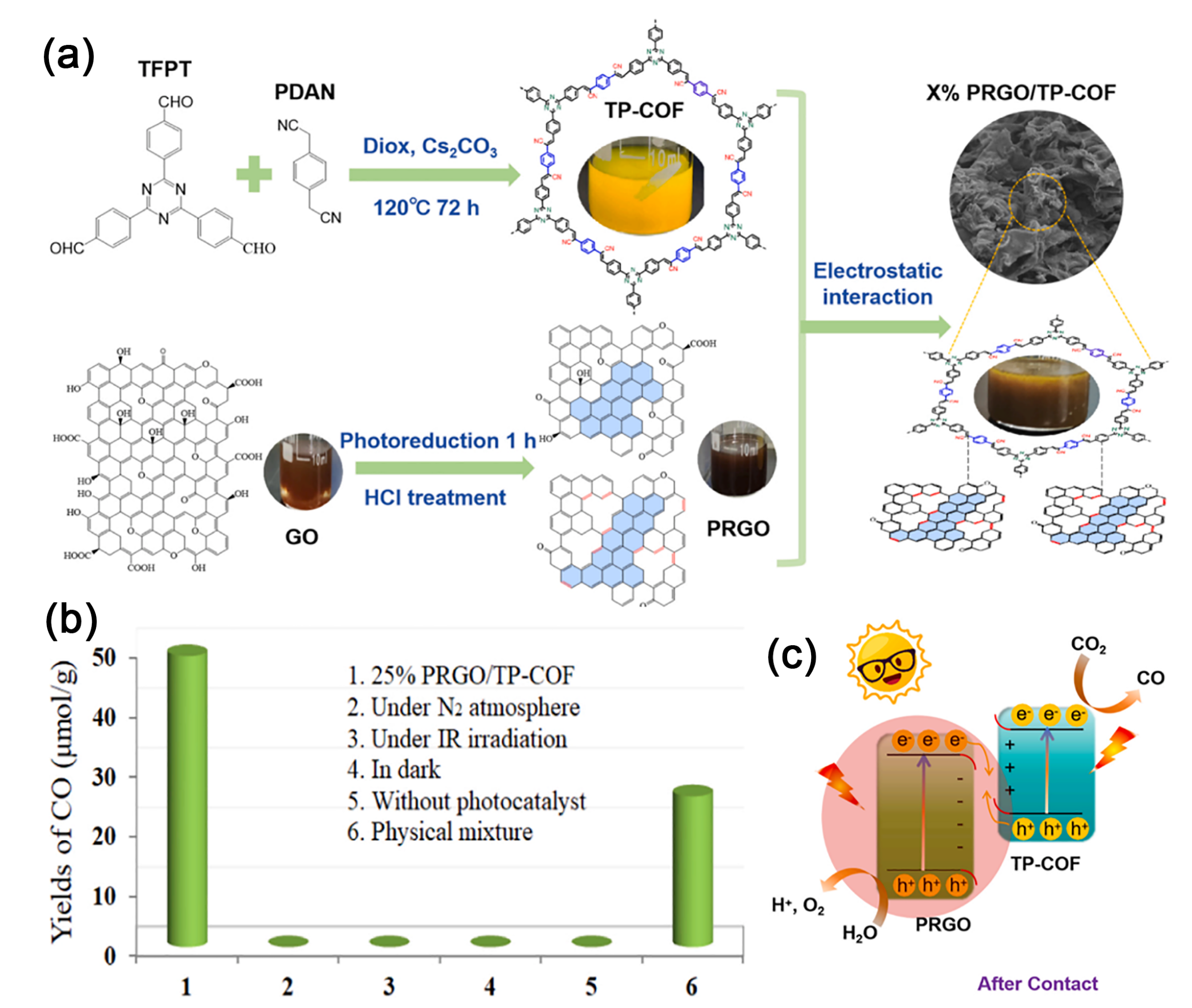
Fig. 11. (a) Synthesis of PRGO/TP-COF Nanocomposites. (b) CO Yield Performance of 25% PRGO/TP-COF under Varied Conditions. (c) Photocatalytic CO2 Reduction by 25% PRGO/TP-COF Nanocomposites. Reprinted with permission from Ref. [88]. Copyright 2024, Elsevier.

Fig. 12. (a) Schematic illustration of the synthesis process for TT-COF/ZCS composites. High-resolution XPS spectra of N 1s (b) and Zn 2p (c) for TT-COF, ZCS, and TZ-40 before and after illumination. (d) Decay pathways of photogenerated electrons in TZ-40. Reprinted with permission from Ref. [90]. Copyright 2024, John Wiley and Sons. (e) Schematic synthesis and porous cage structure of the COF/ZnSe composite. Surface potential of (f) COF and (g) COF/ZnSe-1 under dark and 365 nm light illumination. (h) Schematic relaxation pathways of photogenerated charge carriers in the COF/ZnSe composite. Reprinted with permission from Ref. [93]. Copyright 2025, John Wiley and Sons.
| Photocatalyst | Type | Synthesis method | Application | Light source | Activity | Ref. |
|---|---|---|---|---|---|---|
| COF@CeO2 | Z | in-situ reaction | CO2 reduction | 300 W λ > 420 nm | 66.2 μmol g-1 | [ |
| JUC-X@ZIS | Z | in-situ growth | H2 generation | 10 W LED λ = 420 nm | 9.46 mmol g-1 h-1 | [ |
| TiO2/T-COF | Z | in-situ growth | CO2 reduction | PLS-SXE 300 | 2.3 μmol h-1 | [ |
| Ag3PO4/COF | Z | in-situ synthesis | RhB degradation | 300 W λ > 420 nm | 96.7% (40 min) | [ |
| ZnIn2S4/Tp-Tta COF | S | in-situ growth | organic transformations | LED 80 W | 12.1 mmol g-1 h-1 | [ |
| MAPbBr3/COF | S | self-assembly | organic transformations | blue LED | PTD, 100% | [ |
| Rh-COF@COF | S | in-situ growth | organic transformations | 300 W λ ≥ 420 nm | 2.6 mmol g-1 h-1 | [ |
| W18O49@TpPa-H | S | in-situ growth | organic transformations | 10 W 420 nm LED | 99% within 4 h | [ |
| TpPa-COF/2D g-C3N4 | S | in-situ growth | H2 generation | λ ≥ 420 nm | 17600 μmol g-1 h-1 | [ |
| TB-1 | S | solvothermal | H2O2 production | λ > 420 nm | 723 μmol g-1 h-1 | [ |
| sp2c-COF/Py-NH2-COF | S | solvothermal | purification | 300 W Xe lamp | TC, 94.8%, 1.5 h | [ |
| ZnO/TpPa-Cl | S | in-situ growth | H2O2 production | 300 W Xe lamp | 2443 μmol g-1 h-1 | [ |
| CdS/BiVO4@T-COF | S | self-assembly | CO2 reduction | 300 W 420 ~780 nm | 183.8 μmol g-1 h-1 | [ |
| PRGO/TP-COF | S | self-assembly | CO2 reduction | 300 W λ > 400 nm | 9.76 μmol g-1 h-1 | [ |
| TpMA/In2S3 | S | hydrothermal | H2O2 production | 300 W λ ≥ 420 nm | 311.07 μmol L-1 | [ |
| TiO2/COF | S | in-situ growth | H2O2 production | 300 W 350 ~780 nm | 740 μmol L-1 h-1 | [ |
| g-C3N4(NH)/COF | S | solvothermal | CO2 reduction | 300 W λ > 400 nm | 11.25 μmol h-1 | [ |
| TiO2/TpPa-Cl | S | solvothermal | H2O2 production | 300W 350 ~800 nm | 2082.6 μmol g-1 h-1 | [ |
| COF/Ni-ZIF-8 | S | in-situ growth | CO2 reduction | 300 W λ > 420 nm | 28.7 μmol g-1 h-1 (CH₄) | [ |
| ZnO/COF | S | in-situ growth | H2O2 generation | 365 nm | AQY = 5% | [ |
| BiOBr/COF | S | hydrothermal | degradation | 300 W | 94.6% (120 min) | [ |
| 20N-COF/BOB | S | in-situ growth | TC degradation | 300 W λ > 420 nm | 81.2% (120 min) | [ |
| TiO2/COF | S | in-situ growth | H2 generation | 300 W λ > 380 nm | 3962 μmol g-1 h-1 | [ |
| TpPa-1/MIS-5% | S | in-situ growth | H2 generation | 300 W λ ≥ 420 nm | 13.16 mmol g-1 h-1 | [ |
| CZS-FOCTF | S | hydrothermal | H2 generation | 300 W λ > 420 nm | 247.62 mmol g-1 h-1 | [ |
| MOS2/COF | Type-II | hydrothermal | TC degradation | 300W AM 1.5 | 98% (30 min) | [ |
| CuPor-Ph-COF/g-C3N4 | Type-II | in-situ synthesis | RhB degradation | 300 W λ > 400 nm | 94.5% (90 min) | [ |
| Au2-COF | Schottky junction | deposition | nitrate reduction | 300 W AM 1.5 | 382.48 μmol g-1 h-1 | [ |
Table 1 COF-based heterojunction photocatalysts for various photocatalytic applications.
| Photocatalyst | Type | Synthesis method | Application | Light source | Activity | Ref. |
|---|---|---|---|---|---|---|
| COF@CeO2 | Z | in-situ reaction | CO2 reduction | 300 W λ > 420 nm | 66.2 μmol g-1 | [ |
| JUC-X@ZIS | Z | in-situ growth | H2 generation | 10 W LED λ = 420 nm | 9.46 mmol g-1 h-1 | [ |
| TiO2/T-COF | Z | in-situ growth | CO2 reduction | PLS-SXE 300 | 2.3 μmol h-1 | [ |
| Ag3PO4/COF | Z | in-situ synthesis | RhB degradation | 300 W λ > 420 nm | 96.7% (40 min) | [ |
| ZnIn2S4/Tp-Tta COF | S | in-situ growth | organic transformations | LED 80 W | 12.1 mmol g-1 h-1 | [ |
| MAPbBr3/COF | S | self-assembly | organic transformations | blue LED | PTD, 100% | [ |
| Rh-COF@COF | S | in-situ growth | organic transformations | 300 W λ ≥ 420 nm | 2.6 mmol g-1 h-1 | [ |
| W18O49@TpPa-H | S | in-situ growth | organic transformations | 10 W 420 nm LED | 99% within 4 h | [ |
| TpPa-COF/2D g-C3N4 | S | in-situ growth | H2 generation | λ ≥ 420 nm | 17600 μmol g-1 h-1 | [ |
| TB-1 | S | solvothermal | H2O2 production | λ > 420 nm | 723 μmol g-1 h-1 | [ |
| sp2c-COF/Py-NH2-COF | S | solvothermal | purification | 300 W Xe lamp | TC, 94.8%, 1.5 h | [ |
| ZnO/TpPa-Cl | S | in-situ growth | H2O2 production | 300 W Xe lamp | 2443 μmol g-1 h-1 | [ |
| CdS/BiVO4@T-COF | S | self-assembly | CO2 reduction | 300 W 420 ~780 nm | 183.8 μmol g-1 h-1 | [ |
| PRGO/TP-COF | S | self-assembly | CO2 reduction | 300 W λ > 400 nm | 9.76 μmol g-1 h-1 | [ |
| TpMA/In2S3 | S | hydrothermal | H2O2 production | 300 W λ ≥ 420 nm | 311.07 μmol L-1 | [ |
| TiO2/COF | S | in-situ growth | H2O2 production | 300 W 350 ~780 nm | 740 μmol L-1 h-1 | [ |
| g-C3N4(NH)/COF | S | solvothermal | CO2 reduction | 300 W λ > 400 nm | 11.25 μmol h-1 | [ |
| TiO2/TpPa-Cl | S | solvothermal | H2O2 production | 300W 350 ~800 nm | 2082.6 μmol g-1 h-1 | [ |
| COF/Ni-ZIF-8 | S | in-situ growth | CO2 reduction | 300 W λ > 420 nm | 28.7 μmol g-1 h-1 (CH₄) | [ |
| ZnO/COF | S | in-situ growth | H2O2 generation | 365 nm | AQY = 5% | [ |
| BiOBr/COF | S | hydrothermal | degradation | 300 W | 94.6% (120 min) | [ |
| 20N-COF/BOB | S | in-situ growth | TC degradation | 300 W λ > 420 nm | 81.2% (120 min) | [ |
| TiO2/COF | S | in-situ growth | H2 generation | 300 W λ > 380 nm | 3962 μmol g-1 h-1 | [ |
| TpPa-1/MIS-5% | S | in-situ growth | H2 generation | 300 W λ ≥ 420 nm | 13.16 mmol g-1 h-1 | [ |
| CZS-FOCTF | S | hydrothermal | H2 generation | 300 W λ > 420 nm | 247.62 mmol g-1 h-1 | [ |
| MOS2/COF | Type-II | hydrothermal | TC degradation | 300W AM 1.5 | 98% (30 min) | [ |
| CuPor-Ph-COF/g-C3N4 | Type-II | in-situ synthesis | RhB degradation | 300 W λ > 400 nm | 94.5% (90 min) | [ |
| Au2-COF | Schottky junction | deposition | nitrate reduction | 300 W AM 1.5 | 382.48 μmol g-1 h-1 | [ |
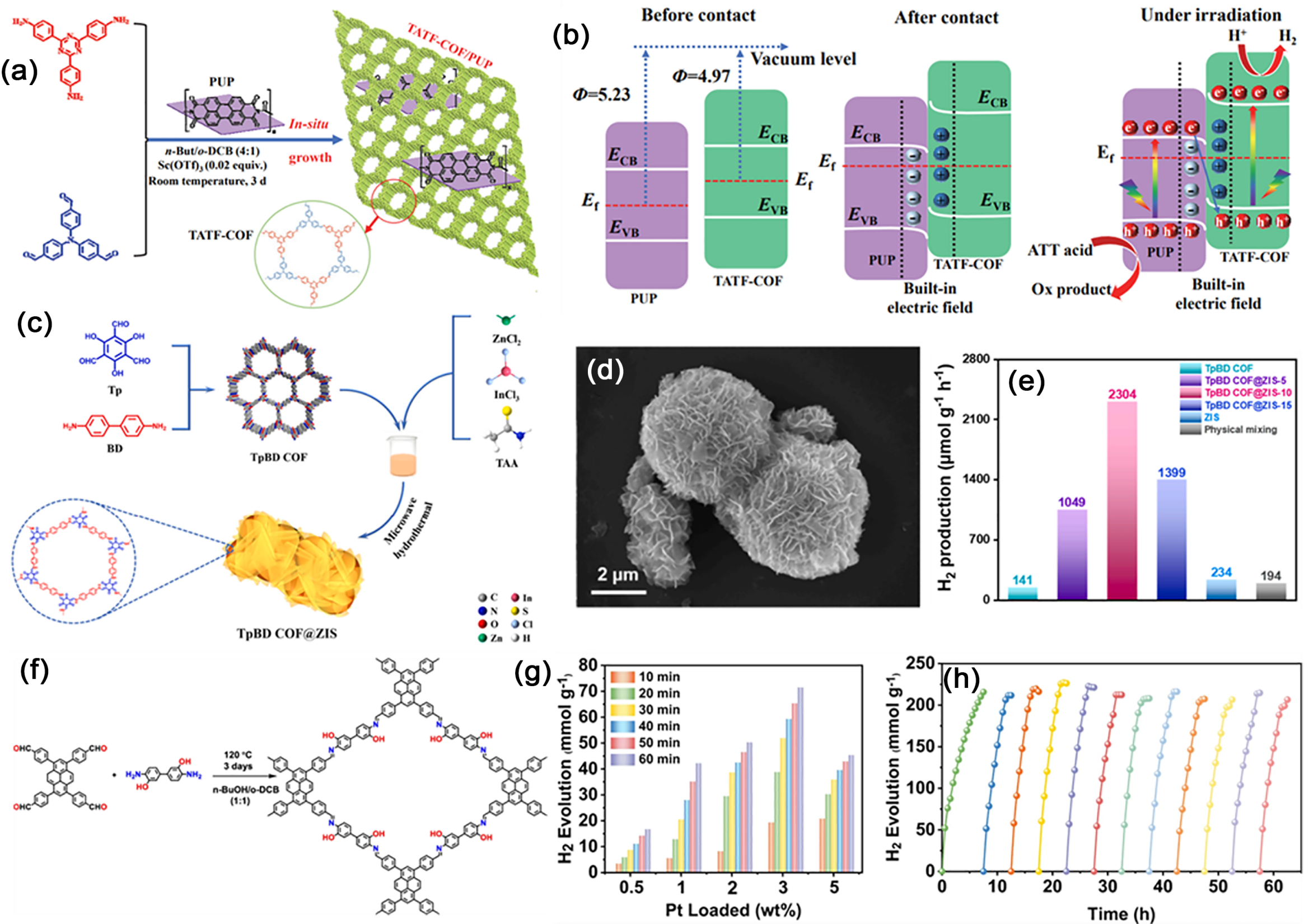
Fig. 13. (a) Synthesis schematic of the TATF COF/PUP heterojunction. (b) Proposed S-scheme mechanism in TATF-COF/PUP heterojunction. Reprinted with permission from Ref. [125]. Copyright 2022, Elsevier. (c) Synthesis of the TpBD COF@ZIS heterojunction. (d) SEM images. (e) H2 production rate versus ZIS loading in TpBD COF@ZIS. Reprinted with permission from Ref. [128]. Copyright 2023, Elsevier. (f) Synthesis process and structure of PY-DHBD-COF. (g) H2 evolution versus time for PY-DHBD-COF with varying Pt loadings. (h) Longterm H2 production for 3 wt% Pt loaded PY-DHBD-COF. Reprinted with permission from Ref. [129]. Copyright 2022, Springer Nature.
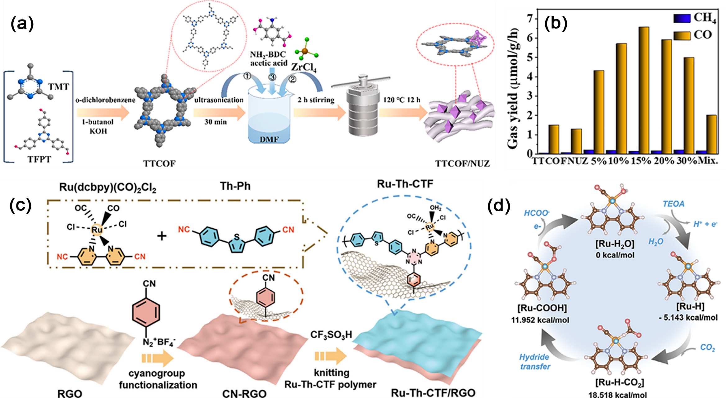
Fig. 14. (a) Preparation of TTCOF/NUZ composites with varying TTCOF contents. (b) Photocatalytic CO2 conversion rates of TTCOF, NUZ, and x% TTCOF/NUZ (x = 5, 10, 15, 20, 30). Reprinted with permission from Ref. [134]. Copyright 2022, American Chemical Society. (c) Schematic illustration of the synthetic route toward Ru-Th-CTF/RGO. (d) Photocatalytic pathway and free energy changes for CO2 reduction to HCOO- on the Ru center. Reprinted with permission from Ref. [135]. Copyright 2023, John Wiley and Sons.
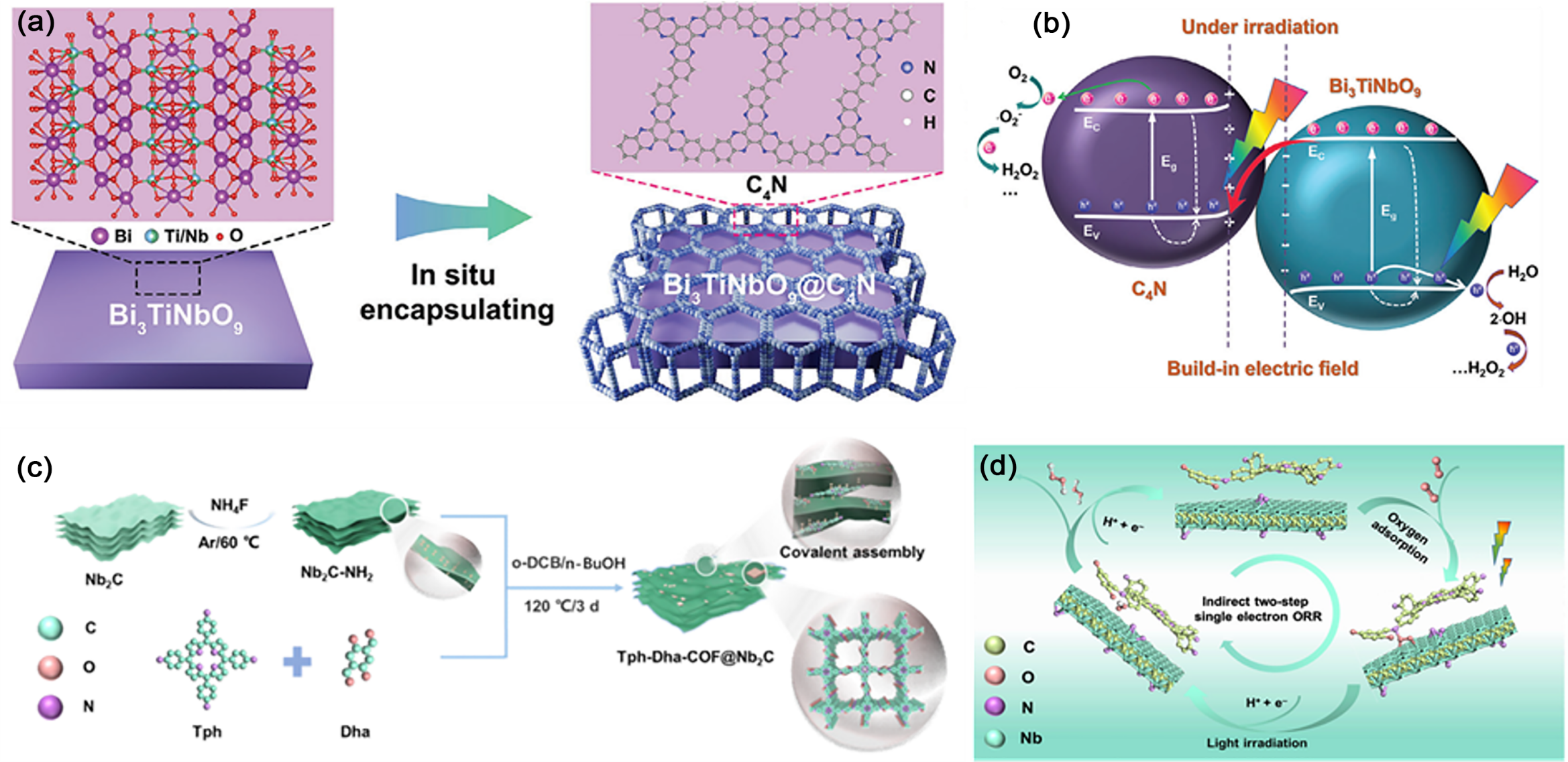
Fig. 15. (a) Schematic of the fabrication process for the Bi3TiNbO9@C4N heterojunction. (b) Schematic of H2O2 photosynthesis coupled with photoinduced charge transfer in the Bi3TiNbO9@C4N heterojunction. Reprinted with permission from Ref. [139]. Copyright 2025, John Wiley and Sons. (c) Schematic illustration of the preparation of the Tph-Dha-COF@Nb2C heterojunction. (d) Proposed 2e- ORR mechanism of H2O2 generation on Tph-Dha-COF@Nb2C. Reprinted with permission from Ref. [140]. Copyright, 2025, Elsevier.

Fig. 16. (a) Schematic synthesis process of the TiO2/TD COF composite. (b) TEM image of the TiO2/TD COF composite. (c) RhB photodegradation over different photocatalyst. (d) Schematic for the decay pathways of photogenerated electrons in TiO2/TD COF heterojunction. Reprinted with permission from Ref. [144]. Copyright, 2025, Elsevier. (e) Synthetic routes and the photo of MT-COF-Au. (f) Possible degradation pathways of BTA in the photocatalytic system. Reprinted with permission from Ref. [146]. Copyright 2024, Elsevier.
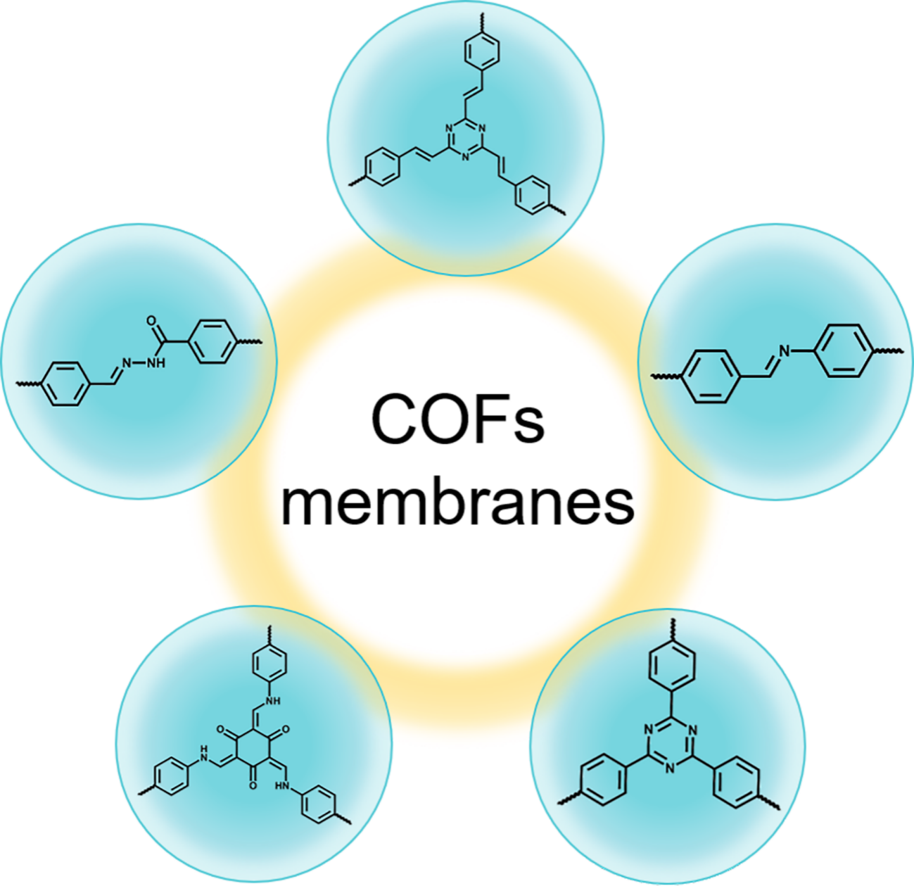
Fig. 17. Representative linkages involved in the COF membranes formation.
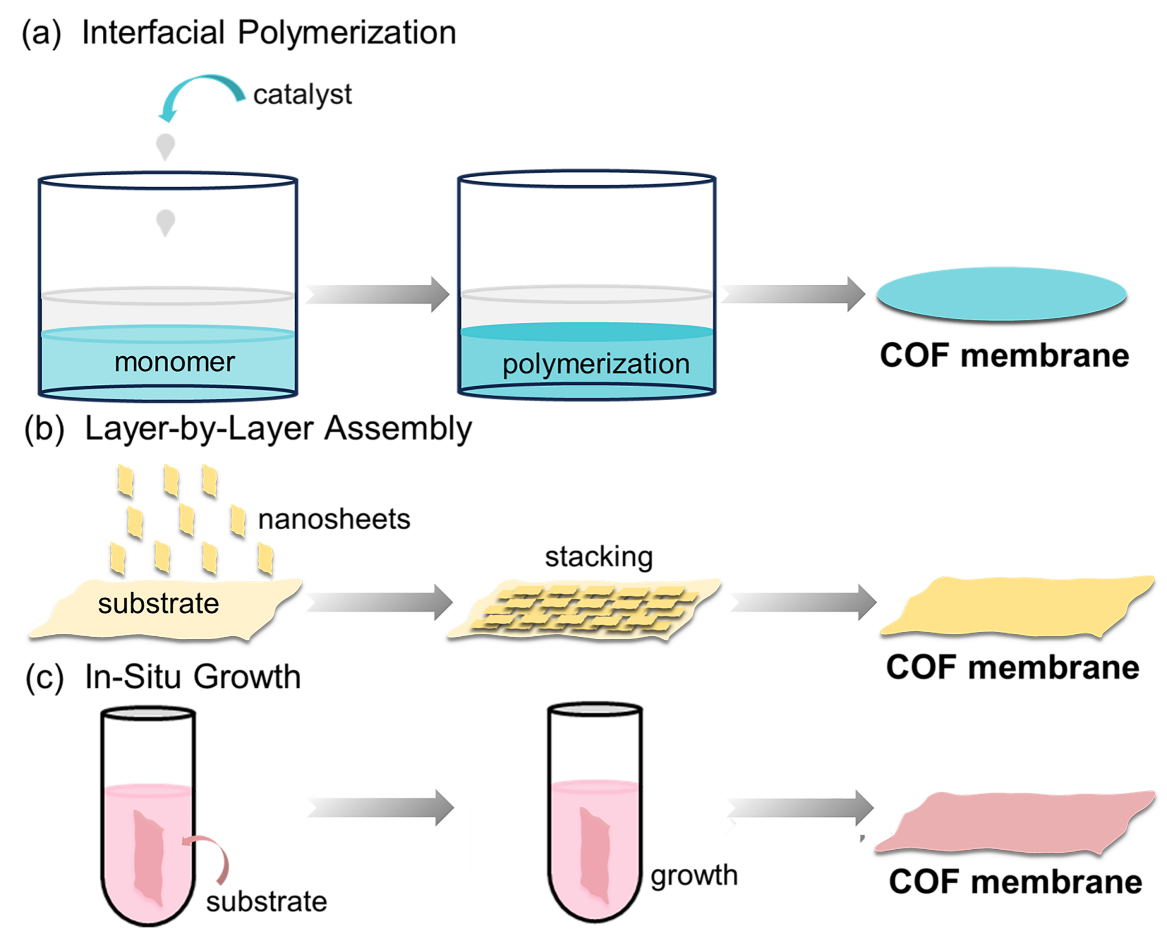
Fig. 18. Schematic illustration of common strategies for COF membrane fabrication. (a) Interfacial polymerization; (b) layer-by-layer assembly; (c) in-situ growth approach.
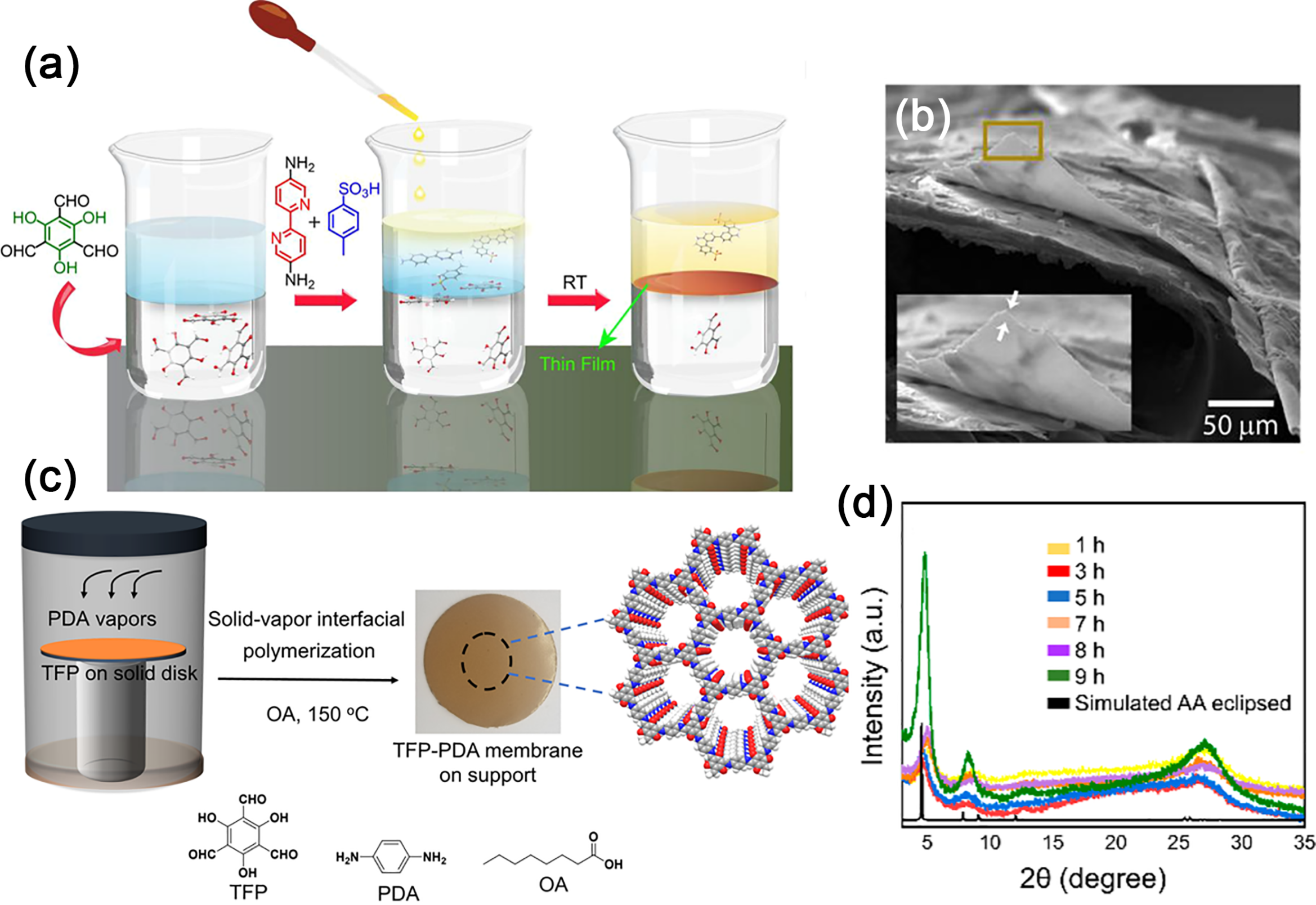
Fig. 19. (a) Synthesis scheme of COF thin membranes. (b) SEM images. Reprinted with permission from Ref. [159]. Copyright 2017, American Chemical Society. (c) Schematic of the COF membrane formation via vapor-solid interfacial reaction. (d) Evolution of XRD patterns of the TFP-PDA membranes over time. Reprinted with permission from Ref. [164]. Copyright 2020, American Chemical Society.
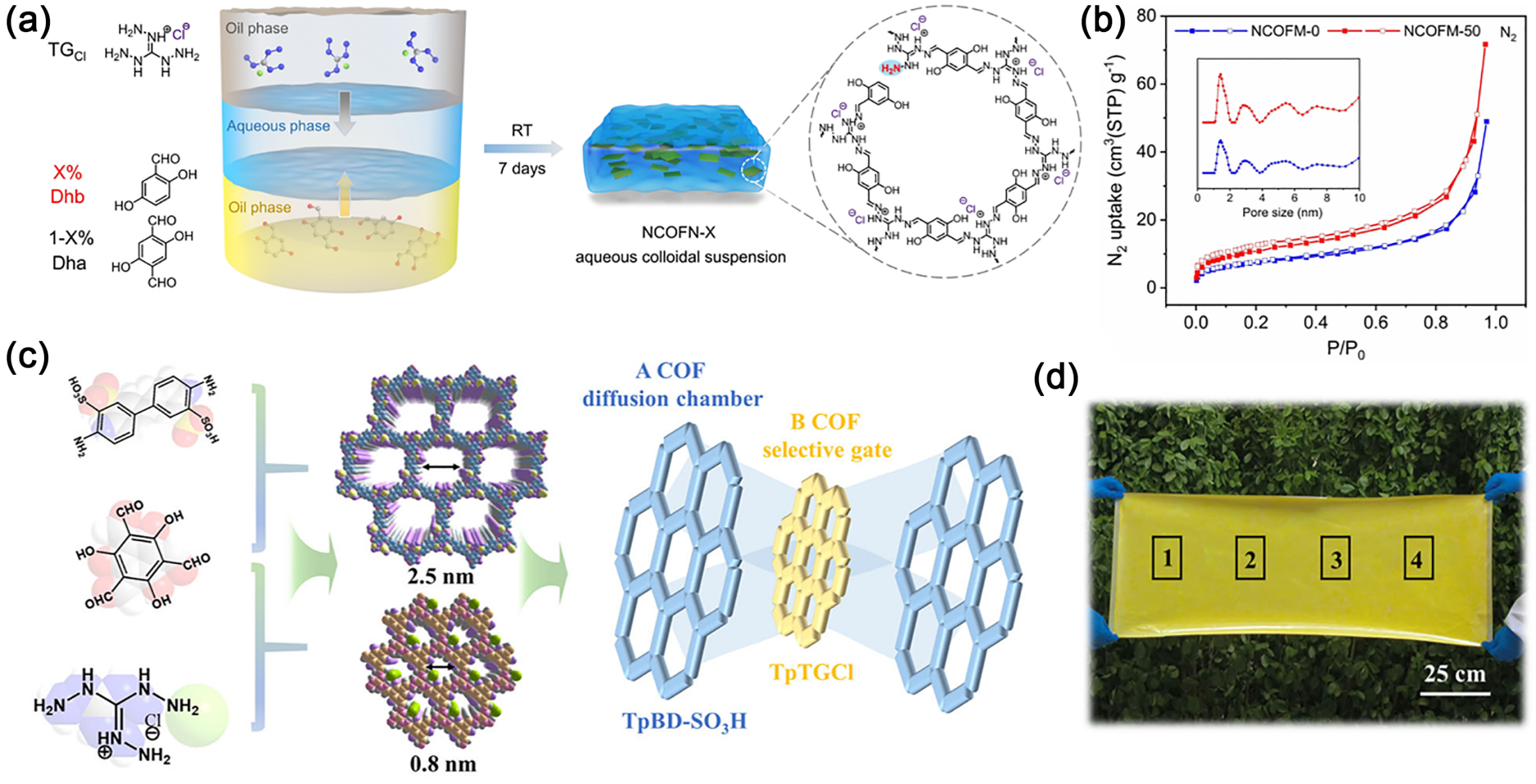
Fig. 20. (a) Synthesis of NCOFN Nanosheets via Oil-Water-Oil Triphase Method. (b) N2 Isotherms (77 K) and Pore Size Distributions of NCOFM-0 and NCOFM-50 Freestanding Membranes. Reprinted with permission from Ref. [169]. Copyright 2022, John Wiley and Sons. (c) Schematic of COF assembly forming an hourglass-shaped channel. (d) Digital photograph of the ultra-large-area membrane. Reprinted with permission from Ref. [171]. Copyright 2025, John Wiley and Sons.
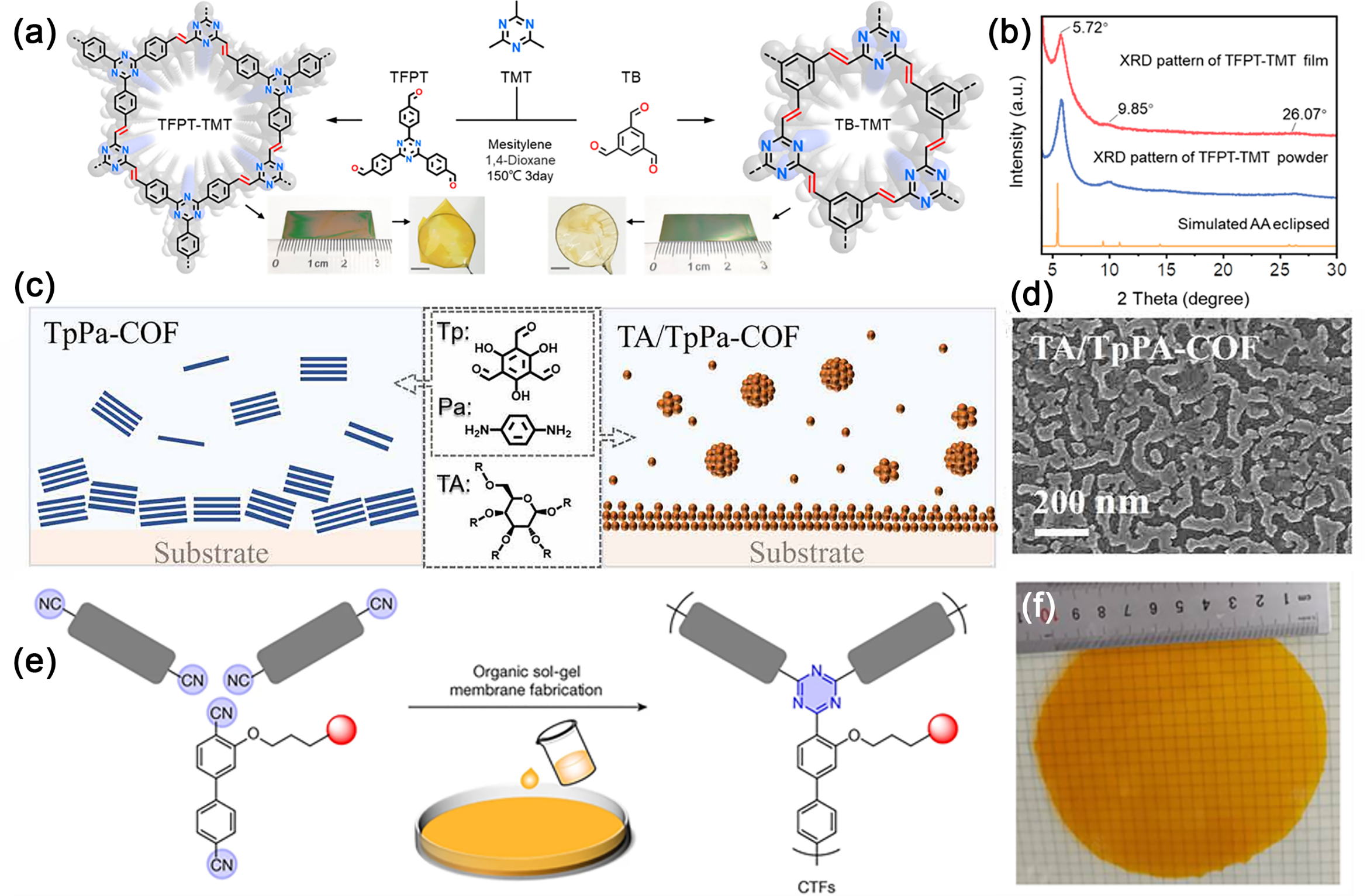
Fig. 21. (a) Synthetic scheme for TB-TMT and TFPT-TMT membranes. (b) XRD patterns of TFPT-TMT membrane, powder, and structure stimulation. Reprinted with permission from Ref. [175]. Copyright 2023, American Chemical Society (c) Surface-initiated growth of a TA/TpPa-COF membrane via TA-mediated nucleation. (d) SEM image of the TA/TpPa-COF membrane surface. Reprinted with permission from Ref. [179]. Copyright 2021, John Wiley and Sons. (e) Schematic structure of CTF membranes. (f) shows a free-standing CTF membrane with a diameter of over 10?cm. Reprinted with permission from Ref. [183]. Copyright 2023, Springer Nature.
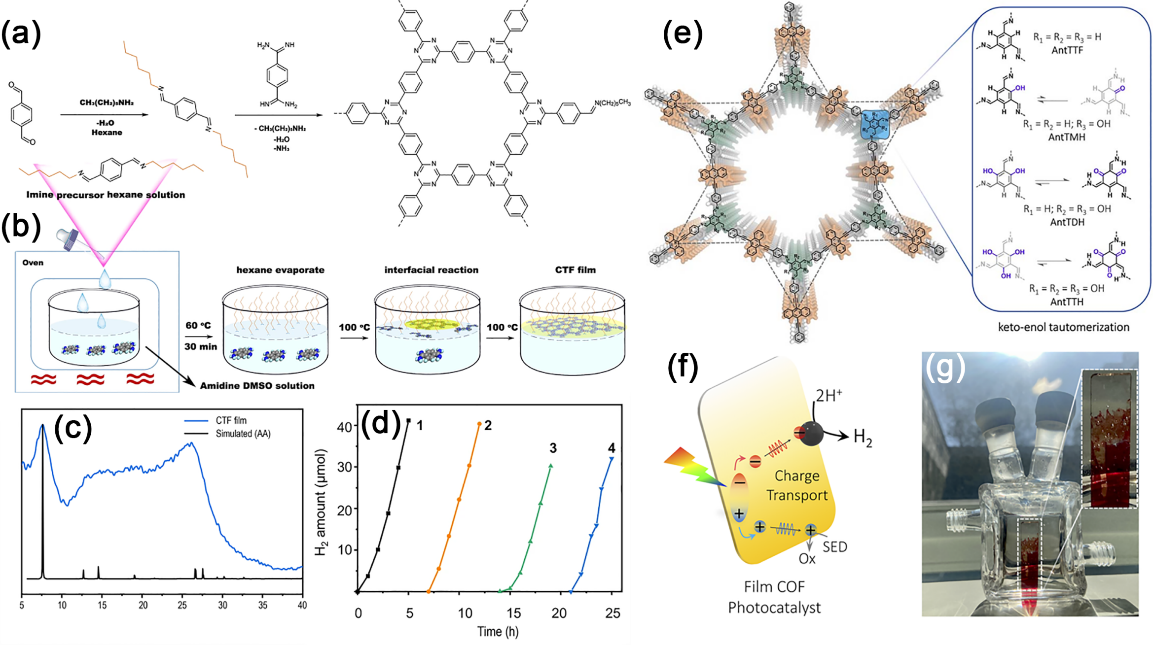
Fig. 22. (a) Reaction steps. (b) Synthetic procedure for the fabrication of CTF membrane on DMSO surface assisted by imine precursor. (c) PXRD of collected CTF membrane and its simulated XRD pattern with AA stacking. (d) Photocatalytic HER performance of membrane on glass in four cycles under visible light (> 420 nm). Reprinted with permission from Ref. [185]. Copyright 2021, Springer Nature. (e) Chemical structures of anthracene-based COFs. (f) Proposed photocatalytic HER mechanism in COF membranes. (g) AntTTH membrane under diffuse sunlight inside a photocatalytic reactor. Reprinted with permission from Ref. [187]. Copyright 2024, Royal Society of Chemistry.
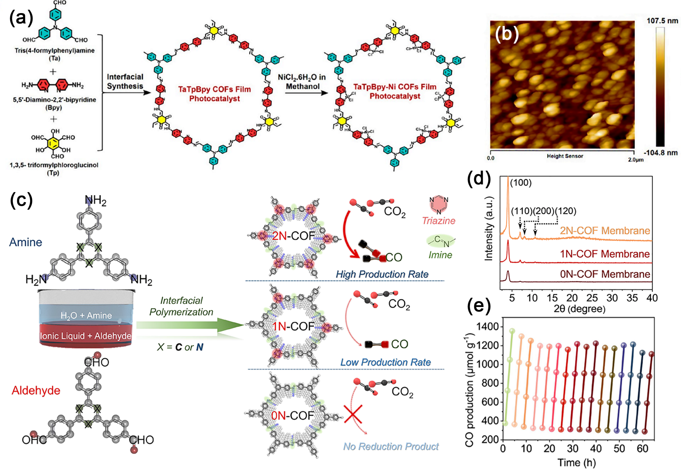
Fig. 23. (a) Synthesis Scheme of a TaTpBpy-Ni COFs membrane Photocatalyst. (b) AFM images of the TaTpBpy-Ni@PET. Reprinted with permission from Ref. [190]. Copyright 2024, American Chemical Society. (c) Schematic illustration for the synthesis of 0N-COF, 1NCOF, and 2N-COF membranes at the ionic liquid-H2O interface. (d) Experimental XRD patterns of the COF membranes. (e) Time courses of the photocatalytic activity and durability based on the 2N-COF membrane. Reprinted with permission from Ref. [191]. Copyright 2023, American Chemical Society.
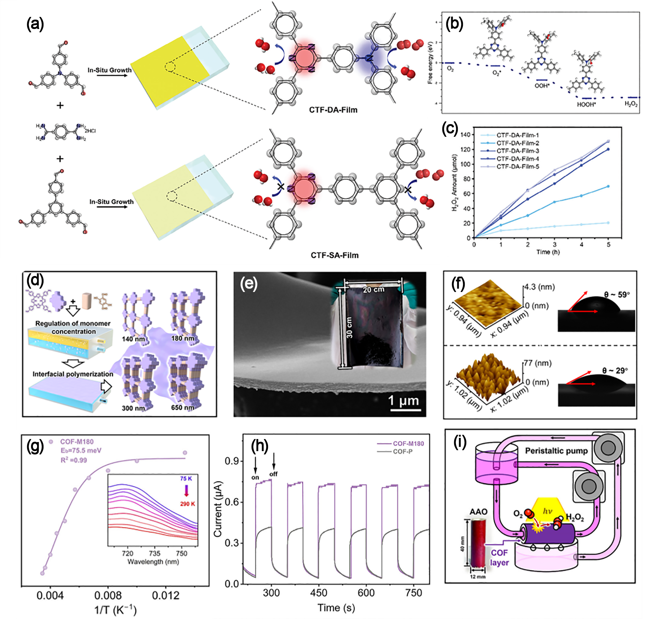
Fig. 24. (a) Schematic formation of CTF-DA-Film and CTF-SA-Film via in-situ polymerization on glass. (b) Free energy of the photocatalytic H2O2 production process over the CTF-DA segment. (c) Production rate of CTF-DA-Film after 1-5 growth cycles. Reprinted with permission from Ref. [194]. Copyright 2024, John Wiley and Sons. (d) Schematic of interfacial polymerization for thickness-tunable COF membrane fabrication. (e) SEM image of COF-M180. Inset: photo of the large-area membrane (20 cm × 30 cm) on PAN. (f) Characterization of surface roughness (AFM) and wettability (contact angle) on both sides of the membrane. (g) Temperature-dependent integrated PL intensity for COF-M180. (h) Photocurrent response measurements of COF-M180 and COF-P. (i) Schematic illustration of the photocatalytic membrane reactor. Reprinted with permission from Ref. [195]. Copyright 2025, John Wiley and Sons.
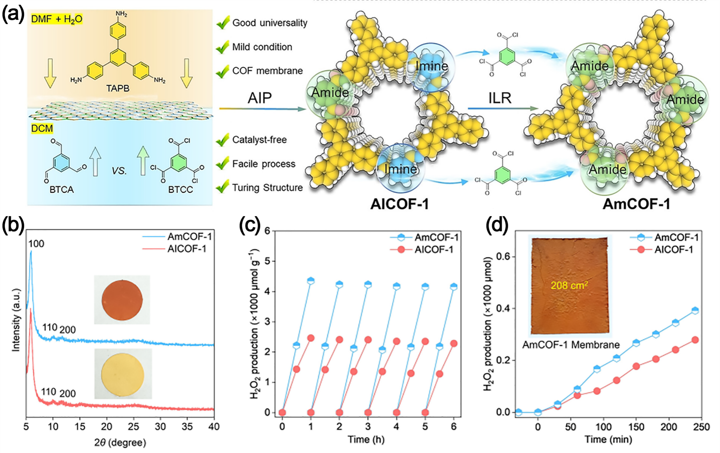
Fig. 25. (a) Synthetic strategy and procedure of the representative AmCOF-1 membrane. (b) XRD patterns. (c) Cyclic H2O2 production over AICOF-1 and AmCOF-1. (d) H2O2 production over AICOF-1 and AmCOF-1 membranes (natural light). Inset: the 208 cm2 AmCOF-1 membrane. Reprinted with permission from Ref. [196]. Copyright 2025, John Wiley and Sons.
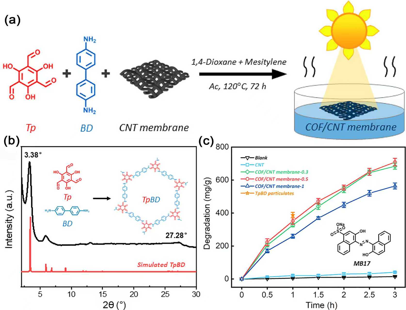
Fig. 26. (a) Diagram of the COF/CNT Membrane Synthesis and the Photocatalytic Degradation Process. (b) PXRD pattern of TpBD. (c) MB17 degradation by various catalysts. Reprinted with permission from Ref. [198]. Copyright 2021, American Chemical Society.
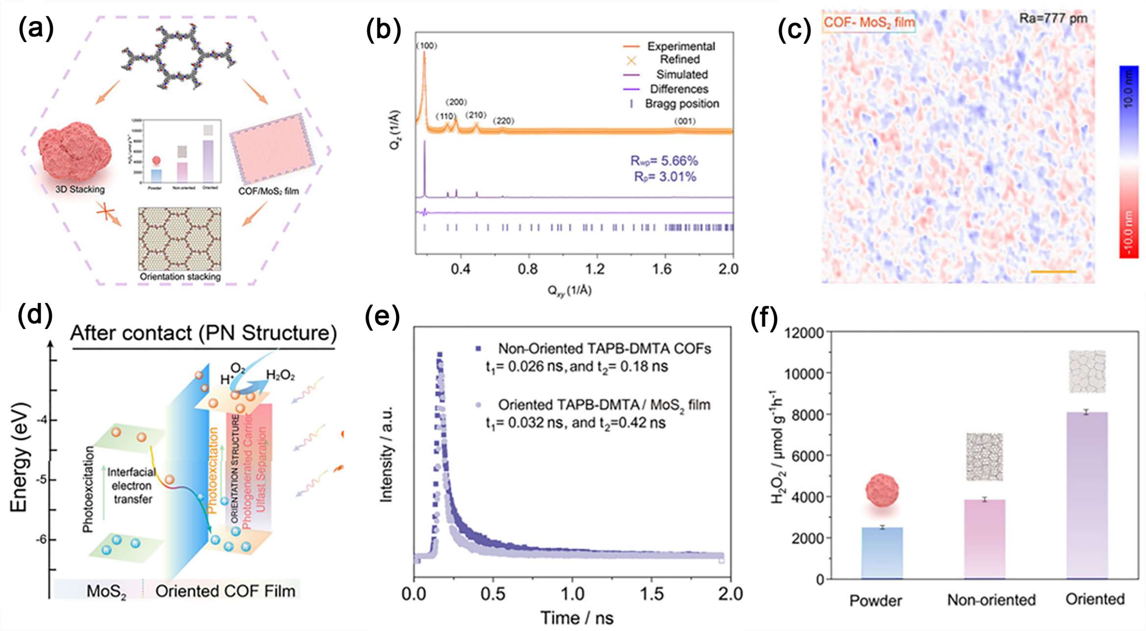
Fig. 27. (a) Schematic illustration of the in-plane oriented COF/MoS2 PN heterostructure membrane. (b) GIXRD pattern and in-plane GIXRD profile of the TAPB-DMTA COF membrane grown on a SiO2/Si substrate. (c) AFM image of a COF membrane grown on a MoS2 substrate. (d) Schematic showing charge separation and photocatalytic H2O2 production in a COF/MoS2 PN heterojunction membrane under visible light. (e) Time-resolved PL decay of oriented TAPB-DMTA/MoS2 membranes and non-oriented TAPT-TFPA COFs. (f) H2O2 production over powder, non-oriented, and oriented TAPB-DMTA COFs. Reprinted with permission from Ref. [203]. Copyright 2025, John Wiley and Sons.
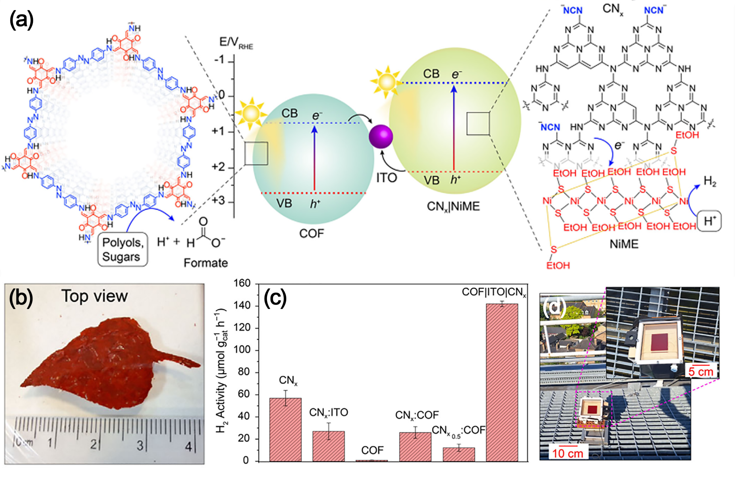
Fig. 28. (a) Energy diagram and schematic of solar reforming over a COF-NiME composite, coupling H2 evolution with oxidation of organics (polyols and sugars) to formate. (b) Photograph of a standalone COF|ITO|CNx. (c) Control experiments for photocatalytic H2 evolution with varied catalyst components and ratios (NiME: 1.25 μmol L-1, H2O, 0.2 mol L-1 EG, 21 h). (d) Photograph of the solar plastic reforming reactor under direct sunlight (inset: close-up view). Reprinted with permission from Ref. [206]. Copyright 2025, John Wiley and Sons.
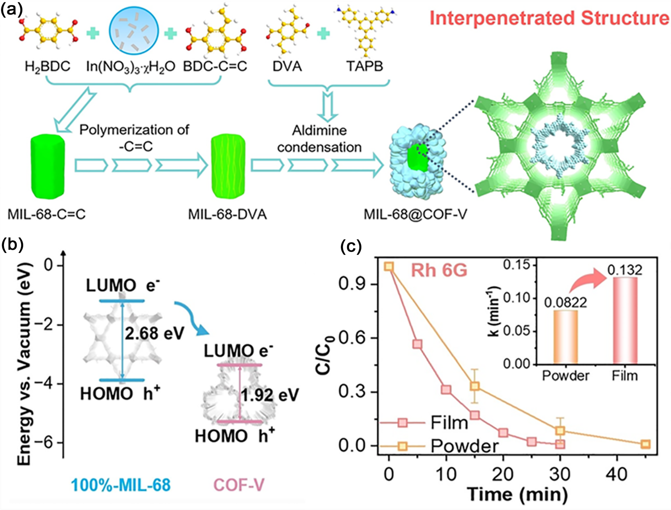
Fig. 29. (a) Schematic illustration of the synthetic process for MIL-68@COF-V heterostructures. (b) Proposed photogenerated electron-transfer pathway within the heterojunction. (c) Comparative degradation of Rh?6G by 10%-MIL-68@COF-V powder and membrane. Reprinted with permission from Ref. [207]. Copyright 2024, John Wiley and Sons.
|
| [1] | Yusuf Bashir Adegbemiga, Jayawardana Hennayaka Mudiyanselage Charitha Madusanka, Yaseen Waleed, 谢吉民, 邓伊琳, 孟素慈, 李永明, Mohammed Abdussamad Mukhtar, Magaji Aminu, 陈敏, 谢萌, 徐远国. 空位工程构筑钌基碳纳米管用于安培级电解水[J]. 催化学报, 2026, 88(9): 279-294. |
| [2] | 朱君江, 许凯强. CdS/NiPc S-型光催化剂及其增强的光催化产过氧化氢性能[J]. 催化学报, 2026, 88(9): 5-8. |
| [3] | 孙宇航, 李旭, 曾众天, 魏华, 赵宇龙, 蔡晓燕, 毛梁, 谭昌龙, 沈博, 徐艺军. 硫诱导电荷位点重构与原位生成ZnO2保护层实现稳定高效的太阳能制备H2O2[J]. 催化学报, 2026, 88(9): 207-217. |
| [4] | 魏耀文, 王建伟, 郭皓, 班涛, 岳玉峰, 胡地, 黄海保. 缺陷UiO-66催化剂在温和条件下实现甲烷高选择性氧化制乙酸[J]. 催化学报, 2026, 88(9): 356-368. |
| [5] | 李东珀, 毛倩倩, 熊超, 系璐颖, 聂宇, 徐啸天, 纪红兵. 构建钌卟啉共价有机框架催化金刚烷C-H键空气氧化接力实现烯烃环氧化[J]. 催化学报, 2026, 88(9): 442-456. |
| [6] | Sathi Chatterjee, 李红梅, 刘康, 林璋, 柴立元, 刘敏. 二维(2D)材料上的单原子催化剂用于光催化CO2还原: 基础、设计与新兴策略[J]. 催化学报, 2026, 88(9): 86-128. |
| [7] | 刘淑芳, 陈锋宇, 李思媛, 叶宇昕, 欧阳钢锋. 氧中心有机自由基最新研究进展: 表征、合成及应用[J]. 催化学报, 2026, 88(9): 183-206. |
| [8] | 雷文敏, 张艳, 孙大琳, 班林, 周恒, 杨松, 景立权, 胡劲光, 张衡. 过渡金属光催化剂用于木质素可持续转化生产生物燃料[J]. 催化学报, 2026, 88(9): 35-85. |
| [9] | 陈翔锋, 黄丝雨, 杨煜杭, 倪嘉浩, 方诚, 徐杨帆, 匡代彬. 卤素钙钛矿材料在杂化光催化中的研究进展[J]. 催化学报, 2026, 88(9): 9-34. |
| [10] | 黄芸, 陈奇, 陈月铃, 杨泽锋, 吴炯桦, 余济美, 吴棱. 在Pt/DUT-67(Zr)表面生成氢物种增强光催化合成氨[J]. 催化学报, 2026, 88(9): 247-258. |
| [11] | 张可可, 张富林, 王月欣, 黄凤伟, 熊康慧, 顾向奎, 郎贤军. 调控亚乙烯基连接的噻吩并噻吩共价有机框架的电子推拉效应以增强选择性光催化[J]. 催化学报, 2026, 87(8): 206-216. |
| [12] | 李世杰, 李蕊, 刘艳萍, 于欣, 马德运, 姜建辉, 周小松, 庄春强, 赵再望, 姜维. Ag/AgBr/C3N5中LSPR增强S型电荷转移促进活性氧物种生成实现高效光催化降解抗生素废水[J]. 催化学报, 2026, 87(8): 126-139. |
| [13] | 李柯, 罗燚, 蔡晨宁, 郑泽民, 余罡, 胡建强, 陈胜利. WN增强金属-N-C载体平台构筑燃料电池用高耐久性Pt基氧还原催化剂[J]. 催化学报, 2026, 87(8): 230-242. |
| [14] | 李博文, 林长霖, 王琪, 伦永烽, 方俊, 宋树芹, 王毅. 配体-壳层工程设计Au25纳米团簇加速CO2电还原生成比例可调的合成气[J]. 催化学报, 2026, 87(8): 396-409. |
| [15] | 郭凤娟, 马春瑶, 黄悦, 杭思彤, 马俊伟, 高洪涛. 远端-交替杂化机制驱动B@Mo2TiC2Tx/MoO2 MXene高效还原N2[J]. 催化学报, 2026, 87(8): 269-281. |
| 阅读次数 | ||||||
|
全文 |
|
|||||
|
摘要 |
|
|||||


