
催化学报 ›› 2027, Vol. 92: 87-114.DOI: 10.1016/S1872-2067(26)65269-2
张博a, 焦玉烨b, 成慧杰b,*( ), 侯军刚b,*()
收稿日期:2026-05-09
接受日期:2026-06-29
出版日期:2027-01-02
发布日期:2026-10-30
通讯作者:
*电子信箱: hjcheng@dlut.edu.cn (成慧杰),基金资助:
Bo Zhanga, Yuye Jiaob, Huijie Chengb,*(), Jungang Houb,*()
Received:2026-05-09
Accepted:2026-06-29
Online:2027-01-02
Published:2026-10-30
Contact:
*E-mail: hjcheng@dlut.edu.cn (H. Cheng),About author:Jungang Hou (School of Chemical Engineering, Dalian University of Technology) received his PhD degree from Tianjin University in 2010. He joined the faculty of University of Science and Technology Beijing and was promoted to associate professor in 2013. He worked in Tohoku University as a fellow of Japan Society for the Promotion of Science (JSPS) from 2014 to 2015. Since 2015, he became a full professor in Dalian University of Technology. His research interests focus on photo(electro)catalytic and electrolytic water splitting and CO2 conversion using renewable energy.
Supported by:摘要:
电催化硝酸根(NO3‒)还原合成氨(NH3)不仅为破解水体硝酸盐污染问题提供了绿色解决方案, 同时实现了污染物向高值化学品的资源化转化, 有望成为传统高能耗Haber‑Bosch工艺的可持续替代路线. 金属有机框架(MOF)材料凭借其高孔隙率、均匀的活性位点以及可调变的有机配体结构, 在电催化领域展现出独特优势. 然而, MOF材料本征导电性差、结构稳定性不足等瓶颈制约其实际应用. 近年来, 通过精细调控MOF材料微观结构, 构建复合材料以及衍生功能材料, 显著提升了NO3‒电还原制氨的催化效率. 因此, 系统梳理MOF材料在该领域的研究进展, 对于揭示MOF结构与催化性能的构效关系、指导高活性电催化剂的设计具有重要价值.
本文系统综述了MOF基电催化剂在NO3‒电还原制氨中的最新研究进展. 首先, 将MOF基催化剂划分为四大类: 单金属MOF、双金属MOF、MOF基复合材料和MOF衍生材料(金属纳米颗粒、金属化合物、单原子/双原子催化剂及多元复合材料), 分别阐述各类材料的结构特征、活性来源及性能差异, 并通过对比汇总典型催化剂的NH3产率、法拉第效率及稳定性, 揭示金属种类、配位环境与催化性能之间的关联. 随后, 重点归纳了提升催化性能的主要调控策略: (1) 形貌结构调控(二维纳米片、三维多孔骨架及模板法构筑大孔结构), 以暴露更多活性位点并加速传质. (2) 串联活性位点构建, 利用双金属或异质组分协同分工, 将NO3‒→NO2‒及NO2‒→NH3两步反应在空间上耦合, 打破单一活性位点的线性比例关系. (3) 有机配体修饰, 通过引入大π共轭配体、调控配位原子种类、缺陷工程及小分子功能化, 优化金属中心的d带中心和电荷分布. (4) 电子结构优化, 基于d带中心理论、晶体场理论和积分晶体轨道哈密顿布居分析, 阐明界面电荷转移、轨道占据及晶界对吸附活化NO3‒和H2O分子解离的影响. 在此基础上, 深入剖析了NO3‒电还原的间接自催化与直接电还原两条路径, 并着重介绍了原位电子顺磁共振、原位傅里叶变换红外光谱、原位拉曼光谱、差分电化学质谱及同步辐射X射线吸收光谱等先进表征技术在捕捉关键中间体(NO3*, NO2*, NO*, NH2*, NHOH*等)、解析反应路径和监测催化剂动态结构演化中的关键作用. 最后, 提出了MOF基催化剂在NO3‒电还原领域中的现状、挑战及未来发展方向.
展望未来, 该领域亟需攻克大电流密度(≥300 mA cm‒2)下的传质与稳定性问题, 发展流动电解槽和膜电极组件; 评价体系应逐步拓展至真实工业废水场景; 同时应降低全电解能耗, 耦合热力学更优的阳极反应; 借助人工智能和机器学习加速高熵MOF等新型催化材料的筛选. 本综述为高性能MOF基NO3‒电还原催化剂的设计提供了系统的理论指导和实验依据, 对推动绿色NH3合成及水污染治理具有重要参考价值.
张博, 焦玉烨, 成慧杰, 侯军刚. 金属有机框架基电催化剂在硝酸根电化学还原制氨中的最新进展[J]. 催化学报, 2027, 92: 87-114.
Bo Zhang, Yuye Jiao, Huijie Cheng, Jungang Hou. Recent advances in metal-organic framework-based electrocatalysts for electrochemical reduction of nitrate to ammonia[J]. Chinese Journal of Catalysis, 2027, 92: 87-114.
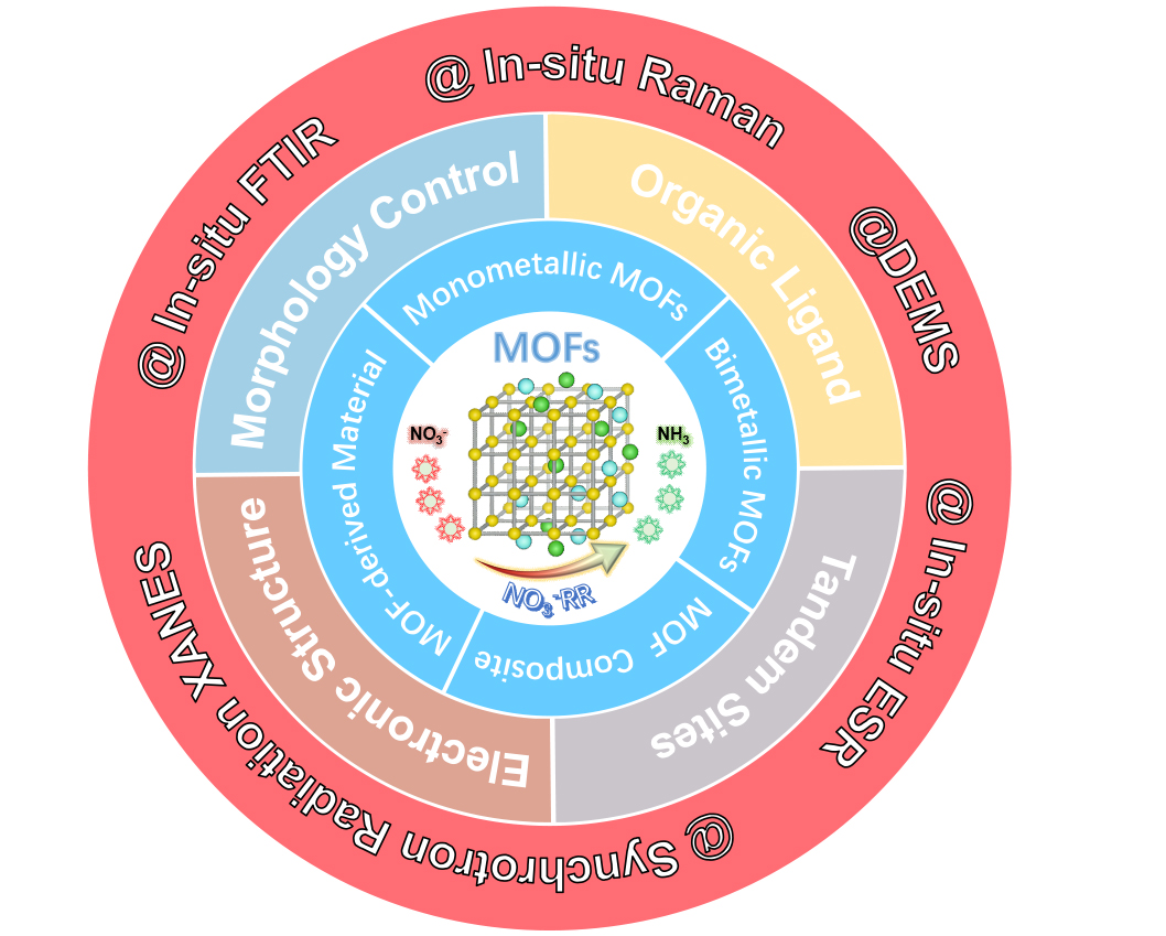
Fig. 1. Schematic illustration of the MOF-based materials for NO3-RR.
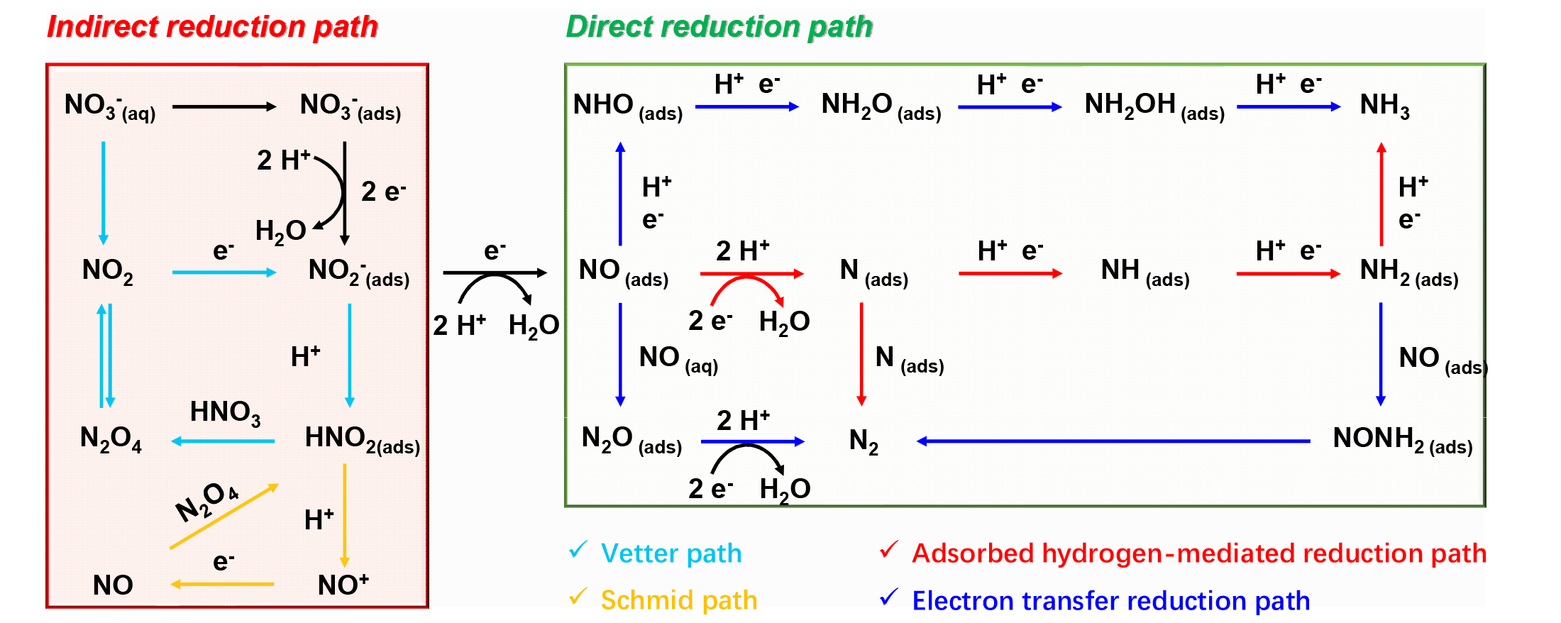
Fig. 2. Schematic diagram of NO3-RR mechanism.
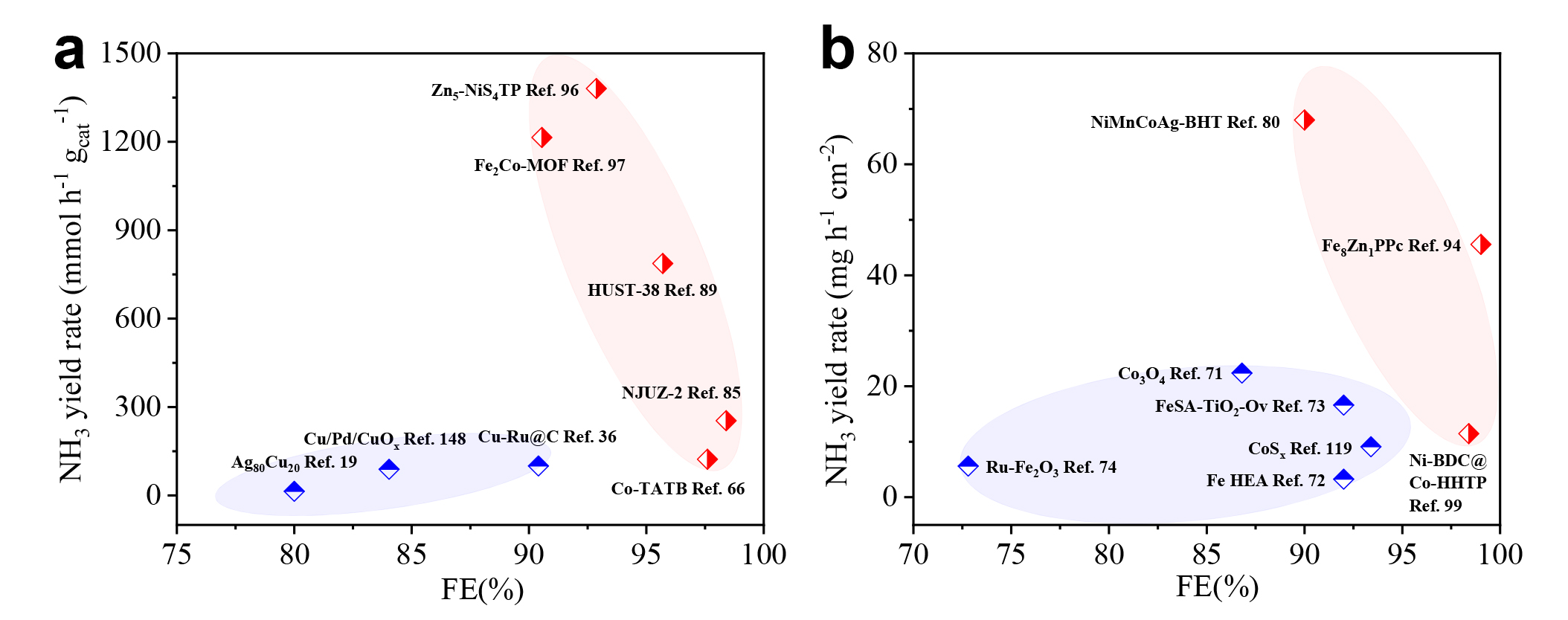
Fig. 3. (a) Comparation of representative MOF catalysts with Cu-based catalysts. (b) Comparation of representative MOF catalysts with Fe- and Co-based catalysts.
| Electrocatalyst | Electrolyte | Potential (V vs. RHE) | NH3 yield | FE (%) | Stability | Ref. |
|---|---|---|---|---|---|---|
| NiCoBDC@HsGDY | 1 mol L‒1 KOH +0.1 mol L‒1 NO3- | -0.34 | 0.56 mmol h-1 cm-2 | 99.1 | 16 cycles | [ |
| Co-TATB | 0.1 mol L‒1 Na2SO4 + 0.1 mol L‒1 KNO3 | -0.7 | 122.7 mmol h-1 gcat-1 | 97.6 | 8 cycles | [ |
| NiMnCoAg-BHT | 1 mol L‒1 KOH + 1 mol L‒1 KNO3 | -0.8 | 68 mg h-1 cm-2 | 90.0 | 15 cycles | [ |
| Cu-CA | 0.1 mol L‒1 Na2SO4 + 0.1 mol L‒1 KNO3 | -0.9 | 286.00 ug h-1 mg-1 | 90.3 | 10 cycles | [ |
| NJUZ-2 | 0.1 mol L‒1 Na2SO4 + 0.1 mol L‒1 KNO3 | -0.8 | 253.7 mmol h-1 gcat-1 | 98.4 | 70 h | [ |
| HUST-38 | 0.5 mol L‒1 K2SO4 + 0.1 mol L‒1 NO3- | -0.6 | 13.38 mg h-1 mgcat-1 | 95.7 | 32 cycles | [ |
| FeCo PBA HCAs | 0.1 mol L‒1 PBS + 0.1 mol L‒1 NaNO3 | -0.6 | 0.105 mmol h-1 cm-2 | 81.01 | 5 cycles | [ |
| Fe8Zn1PPc | 1 mol L‒1 NaOH + 0.5 mol L‒1 NaNO3 | -0.85 | 2.68 mmol h-1 cm-2 | 99.02 | 120 h | [ |
| Cu1Co1HHTP | 0.5 mol L‒1 Na2SO4 + 0.1 mol L‒1 NaNO3 | -0.6 | 299.9 μmol h-1 cm-2 | 96.4 | 7 cycles | [ |
| Zn5-NiS4TP | 0.05 mol L‒1 K2SO4 + 0.5 mol L‒1 KNO3 | -1.2 | 23477.59 ug h-1 mgcat-1 | 92.87 | 20 cycles | [ |
| Ni-BDC@Co-HHTP | 1 mol L‒1 NaOH + 0.1 mol L‒1 NaNO3 | -0.7 | 11.46 mg h-1 cm-2 | 98.4 | 10 cycles | [ |
| 1-Cu’ | 0.5 mol L‒1 Na2SO4 + 5 mmol L‒1 NaNO3 | -0.9 | 66 μmol h-1 cm-2 | 85.5 | 12 cycles | [ |
| CoP/Zn-ZIF | 0.5 mol L‒1 Na2SO4 + 0.1 mol L‒1 NaNO3 | -1 | 0.89 mmol h-1 cm-2 | 97.2 | 30 cycles | [ |
| Cu@C-800 | 0.1 mol L‒1 Na2SO4+500 ppm NO3- | -0.9 | 51.7 mmol h-1 cm-2 | 78 | — | [ |
| CoSx | 1 mol L‒1 NaOH + 0.1 mol L‒1 NaNO3 | -0.5 | 9.1 mg h-1 cm-2 | 93.4 | 5 cycles | [ |
| Cu/Co0.85SeVSe | 0.1 mol L‒1 KOH + 0.01 mol L‒1 NO3- | -0.6 | 2360 ug h-1 cm-2 | 93.5 | 600 h | [ |
| Co-TPA-E | 1 mol L‒1 KOH + 0.1 mol L‒1 KNO3 | -0.326 | 1.12 mmol h-1 cm-2 | 99.62 | 15 cycles | [ |
| Cu/NC | 0.5 mol L‒1 Na2SO4+200 ppm NO3- | -0.7 | 32300 ug h-1 mgcat-1 | 100 | 20 cycles | [ |
| Fe-N/P-C | 0.1 mol L‒1 KOH + 0.1 mol L‒1 KNO3 | -0.4 | 17980 ug h-1 mgcat-1 | 90.3 | 20 cycles | [ |
| CoRu/Pd/PCNFs | 0.1 mol L‒1 KOH + 0.1 mol L‒1 KNO3 | -0.6 | 78 umol h-1 mgcat-1 | 98.69 | 100 h | [ |
| Fe-cyano NSs | 1 mol L‒1 KOH + 0.1 mol L‒1 KNO3 | -0.5 | 42.1 mg h-1 mgcat-1 | 90.2 | 8 cycles | [ |
| Cu99Ni1-DBCO | 0.1 mol L‒1 KHCO3 + 0.05 mol L‒1 KNO3 | -1.1 | 159.4 ug h-1 mgcat-1 | 80 | 60 h | [ |
Table 1 Summary of recently reported pristine MOFs, MOF composites, and MOF derivatives for NO3-RR.
| Electrocatalyst | Electrolyte | Potential (V vs. RHE) | NH3 yield | FE (%) | Stability | Ref. |
|---|---|---|---|---|---|---|
| NiCoBDC@HsGDY | 1 mol L‒1 KOH +0.1 mol L‒1 NO3- | -0.34 | 0.56 mmol h-1 cm-2 | 99.1 | 16 cycles | [ |
| Co-TATB | 0.1 mol L‒1 Na2SO4 + 0.1 mol L‒1 KNO3 | -0.7 | 122.7 mmol h-1 gcat-1 | 97.6 | 8 cycles | [ |
| NiMnCoAg-BHT | 1 mol L‒1 KOH + 1 mol L‒1 KNO3 | -0.8 | 68 mg h-1 cm-2 | 90.0 | 15 cycles | [ |
| Cu-CA | 0.1 mol L‒1 Na2SO4 + 0.1 mol L‒1 KNO3 | -0.9 | 286.00 ug h-1 mg-1 | 90.3 | 10 cycles | [ |
| NJUZ-2 | 0.1 mol L‒1 Na2SO4 + 0.1 mol L‒1 KNO3 | -0.8 | 253.7 mmol h-1 gcat-1 | 98.4 | 70 h | [ |
| HUST-38 | 0.5 mol L‒1 K2SO4 + 0.1 mol L‒1 NO3- | -0.6 | 13.38 mg h-1 mgcat-1 | 95.7 | 32 cycles | [ |
| FeCo PBA HCAs | 0.1 mol L‒1 PBS + 0.1 mol L‒1 NaNO3 | -0.6 | 0.105 mmol h-1 cm-2 | 81.01 | 5 cycles | [ |
| Fe8Zn1PPc | 1 mol L‒1 NaOH + 0.5 mol L‒1 NaNO3 | -0.85 | 2.68 mmol h-1 cm-2 | 99.02 | 120 h | [ |
| Cu1Co1HHTP | 0.5 mol L‒1 Na2SO4 + 0.1 mol L‒1 NaNO3 | -0.6 | 299.9 μmol h-1 cm-2 | 96.4 | 7 cycles | [ |
| Zn5-NiS4TP | 0.05 mol L‒1 K2SO4 + 0.5 mol L‒1 KNO3 | -1.2 | 23477.59 ug h-1 mgcat-1 | 92.87 | 20 cycles | [ |
| Ni-BDC@Co-HHTP | 1 mol L‒1 NaOH + 0.1 mol L‒1 NaNO3 | -0.7 | 11.46 mg h-1 cm-2 | 98.4 | 10 cycles | [ |
| 1-Cu’ | 0.5 mol L‒1 Na2SO4 + 5 mmol L‒1 NaNO3 | -0.9 | 66 μmol h-1 cm-2 | 85.5 | 12 cycles | [ |
| CoP/Zn-ZIF | 0.5 mol L‒1 Na2SO4 + 0.1 mol L‒1 NaNO3 | -1 | 0.89 mmol h-1 cm-2 | 97.2 | 30 cycles | [ |
| Cu@C-800 | 0.1 mol L‒1 Na2SO4+500 ppm NO3- | -0.9 | 51.7 mmol h-1 cm-2 | 78 | — | [ |
| CoSx | 1 mol L‒1 NaOH + 0.1 mol L‒1 NaNO3 | -0.5 | 9.1 mg h-1 cm-2 | 93.4 | 5 cycles | [ |
| Cu/Co0.85SeVSe | 0.1 mol L‒1 KOH + 0.01 mol L‒1 NO3- | -0.6 | 2360 ug h-1 cm-2 | 93.5 | 600 h | [ |
| Co-TPA-E | 1 mol L‒1 KOH + 0.1 mol L‒1 KNO3 | -0.326 | 1.12 mmol h-1 cm-2 | 99.62 | 15 cycles | [ |
| Cu/NC | 0.5 mol L‒1 Na2SO4+200 ppm NO3- | -0.7 | 32300 ug h-1 mgcat-1 | 100 | 20 cycles | [ |
| Fe-N/P-C | 0.1 mol L‒1 KOH + 0.1 mol L‒1 KNO3 | -0.4 | 17980 ug h-1 mgcat-1 | 90.3 | 20 cycles | [ |
| CoRu/Pd/PCNFs | 0.1 mol L‒1 KOH + 0.1 mol L‒1 KNO3 | -0.6 | 78 umol h-1 mgcat-1 | 98.69 | 100 h | [ |
| Fe-cyano NSs | 1 mol L‒1 KOH + 0.1 mol L‒1 KNO3 | -0.5 | 42.1 mg h-1 mgcat-1 | 90.2 | 8 cycles | [ |
| Cu99Ni1-DBCO | 0.1 mol L‒1 KHCO3 + 0.05 mol L‒1 KNO3 | -1.1 | 159.4 ug h-1 mgcat-1 | 80 | 60 h | [ |
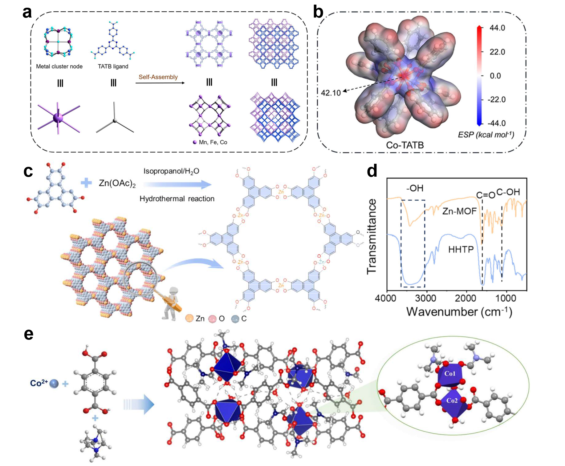
Fig. 4. (a) Schematic representation of the structural assembly process and crystal structures of the high-symmetry coordination MOPs (M = Mn, Fe, or Co). (b) Electrostatic potential (ESP) surface of the Co-TATB model. Reprinted with permission from Ref. [66]. Copyright 2025, American Chemical Society. (c) Schematic illustration of Zn-MOF sample synthesis. (d) Infrared spectra of Zn-MOF and HHTP samples. Reprinted with permission from Ref. [88]. Copyright 2026, Elsevier. (e) Schematic representation of the synthesis, molecular structure, and coordination network within the crystal lattice of HUST-38. Reprinted with permission from Ref. [89]. Copyright 2025, American Chemical Society.
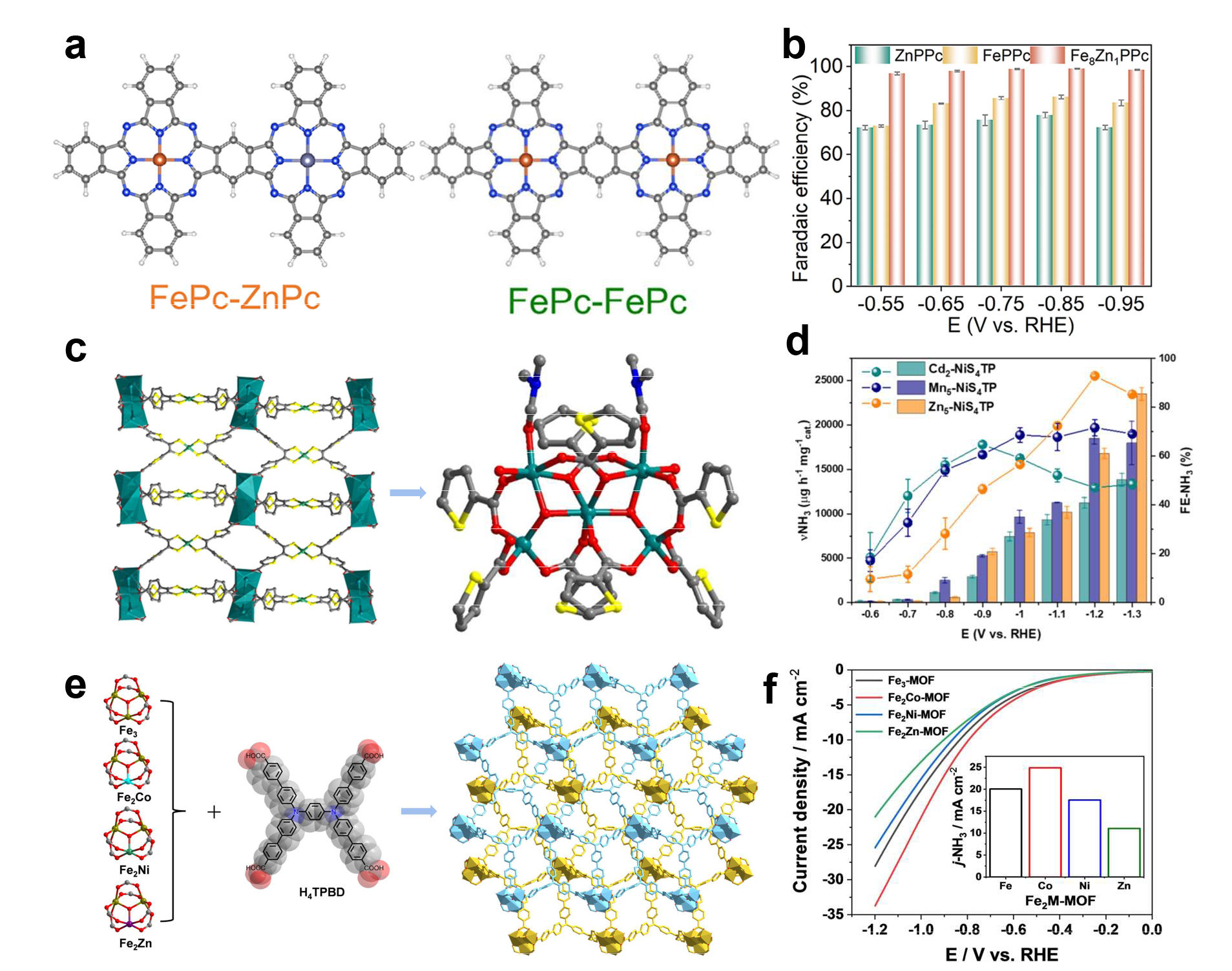
Fig. 5. (a) The computational structure models of FePc-FePc and FePc-ZnPc. (b) FENH3 of FePPc, ZnPPc and Fe8Zn1PPC. Reprinted with permission from Ref. [94], Copyright 2025, John Wiley and Sons. (c) Crystal structure of the ligand and view of the three-dimensional structure in the bc plane and coordination environments of Zn5-NiS4TP. (d) NH3 yield rates and the corresponding FEs-NH3 of the Zn5-NiS4TP, Mn5-NiS4TP and Cd2-NiS4TP at selected potentials in 0.05 mol L-1 K2SO4 with 0.5 mol L-1 KNO3. Reprinted with permission from Ref. [96]. Copyright 2025, John Wiley and Sons. (e) 3D framework of Fe2M-MOF with different trinuclear metal clusters and the H4TPBD ligand. (f) LSV curves of Fe2M-MOFs in 0.05 mol L-1 (pH = 1) H2SO4 with 50 g L-1 KNO3 electrolytes. Reprinted with permission from Ref. [97]. Copyright 2023, John Wiley and Sons.
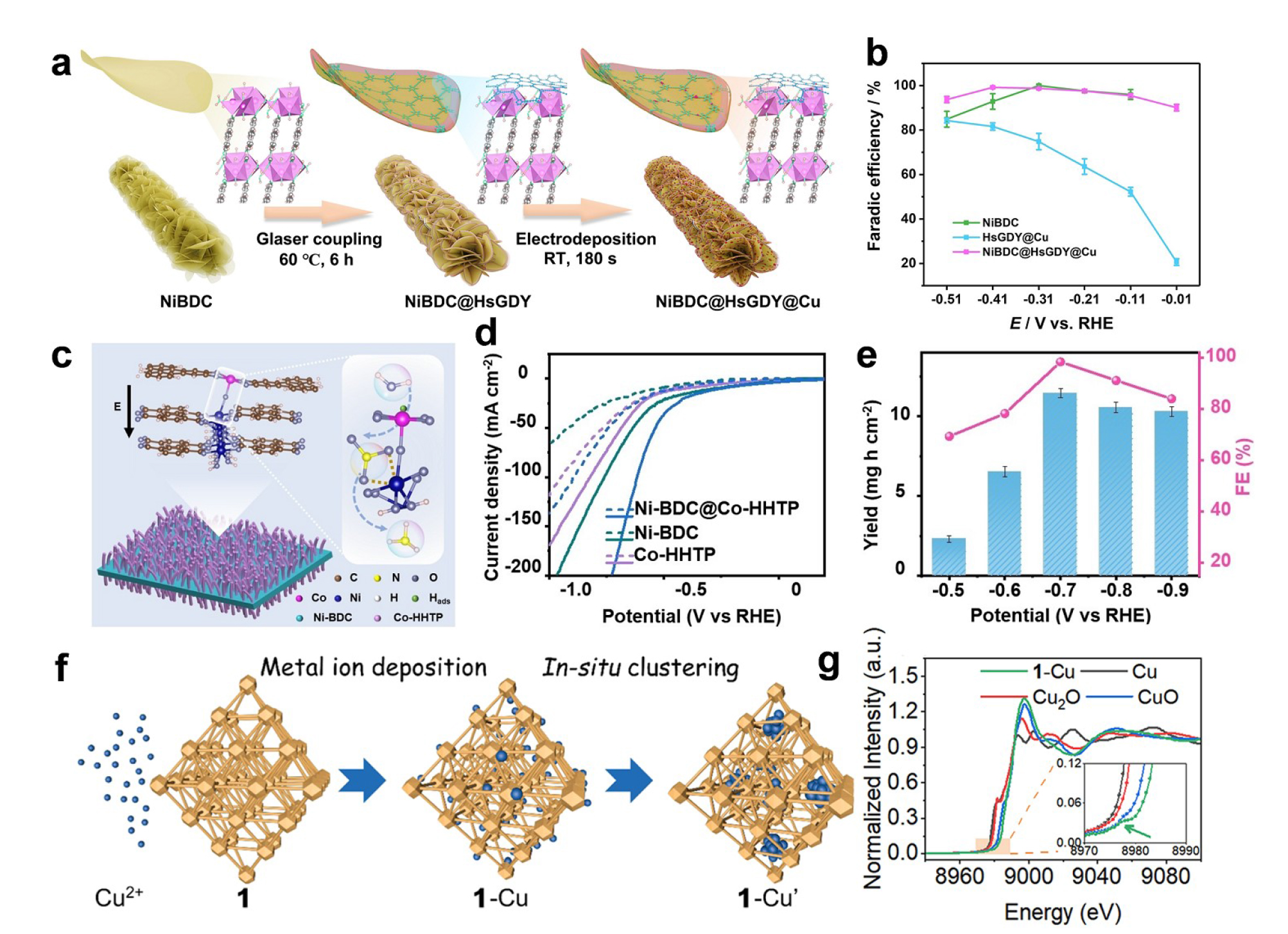
Fig. 6. (a) Schematic illustration of the joining of ultrathin Ni-MOF nanosheets with few-layered HsGDY-supported Cu single atoms and clusters. (b) FENH3 of NiBDC, HsGDY@Cu and NiBDC@HsGDY@Cu. Reprinted with permission from Ref. [98]. Copyright 2024, John Wiley and Sons. (c) Illustration of NO3‒RR to NH3 production over Ni-BDC@Co-HHTP heterostructured MOF-on-MOF electrocatalyst. (d) LSV curves in 1 mol L‒1 KOH electrolyte with and without NO3‒. (e) The NH3 yield rate and FE of Ni-BDC@Co-HHTP at different potentials. Reprinted with permission from Ref. [99]. Copyright 2024, John Wiley and Sons. (f) Preparation and evolution of the host-guest Cu catalyst through metal ion deposition and in-situ clustering routes. (g) Normalized XANES of 1-Cu’. Reprinted with permission from Ref. [104]. Copyright 2022, American Chemical Society.
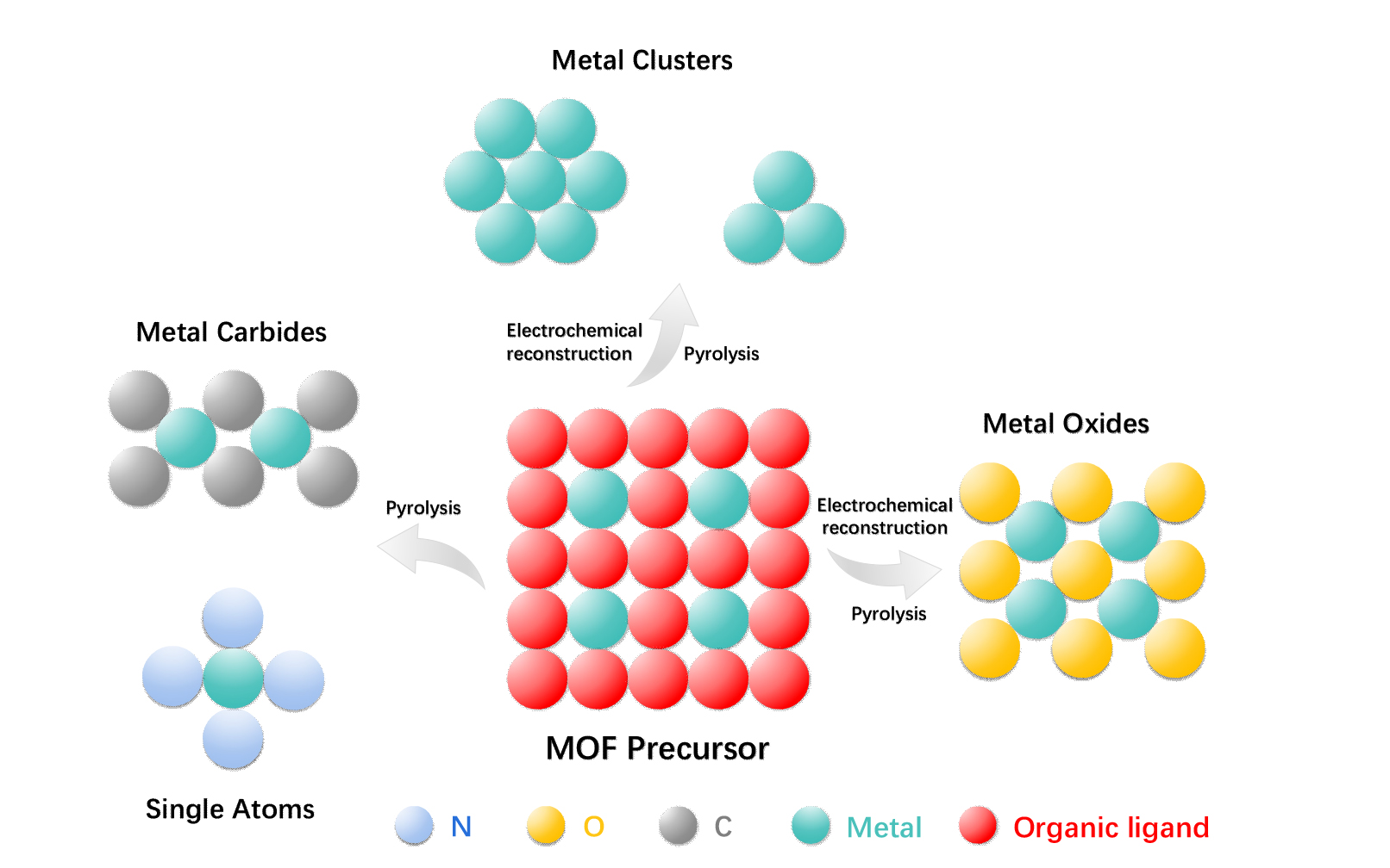
Fig. 7. Schematic illustration of taking MOF materials as precursor to prepare metal clusters, metal oxides, metal carbides and single-atom catalysts by means of electrochemical reconstruction or pyrolysis.
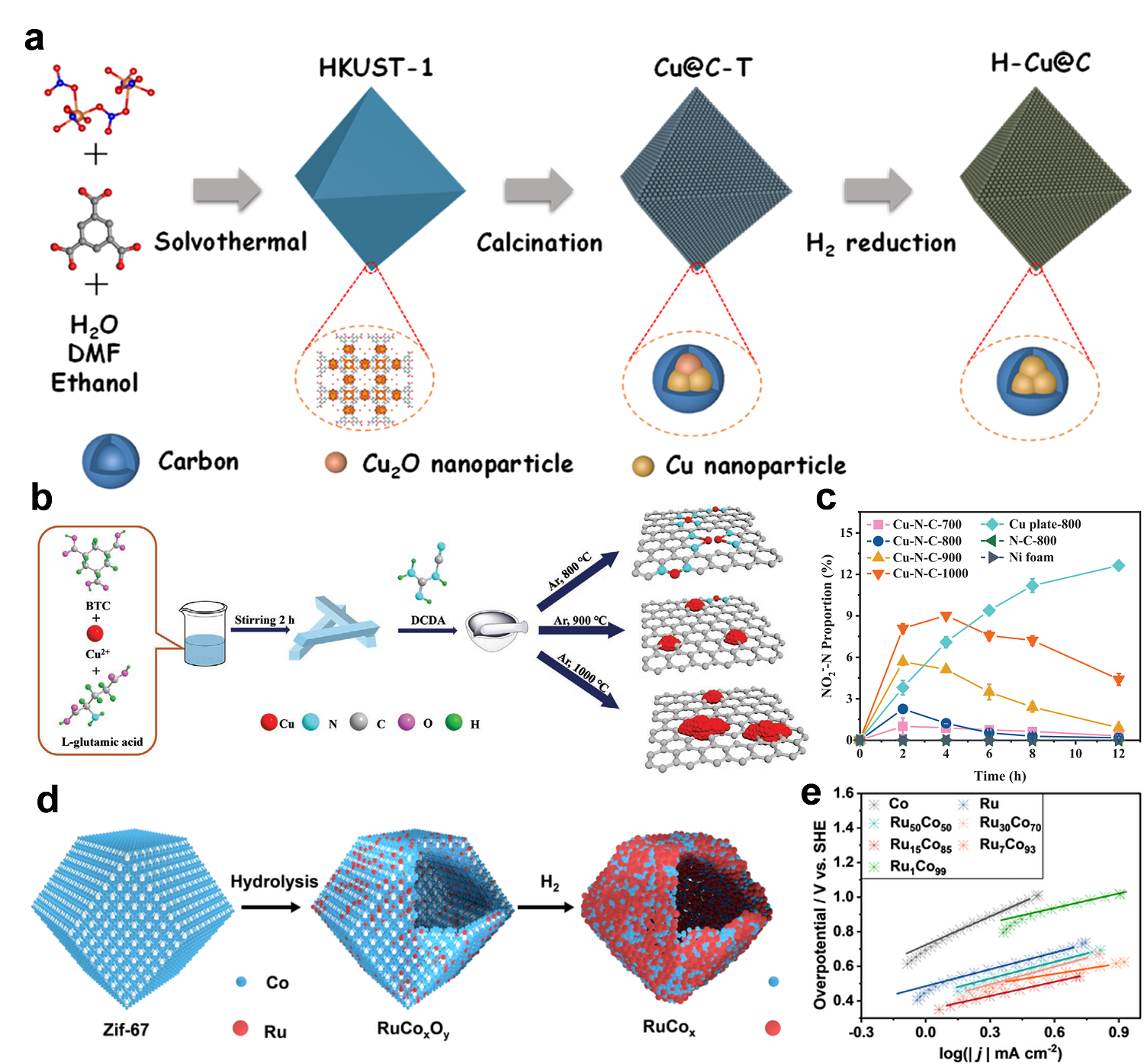
Fig. 8. (a) Schematic illustration of the preparation of HKUST-1. Reprinted with permission from Ref. [112], Copyright 2022, American Chemical Society. (b) Schematic illustration of the synthesis process for Cu-N-C-T. (c) Time-course NO2--N proportion. Reprinted with permission from Ref. [114]. Copyright 2020, John Wiley and Sons. (d) Schematic illustration of RuxCoy HNDs synthesis. (e) Tafel slopes of NO3-RR over RuxCoy HNDs. Reprinted with permission from Ref. [117]. Copyright 2023, Springer Nature.
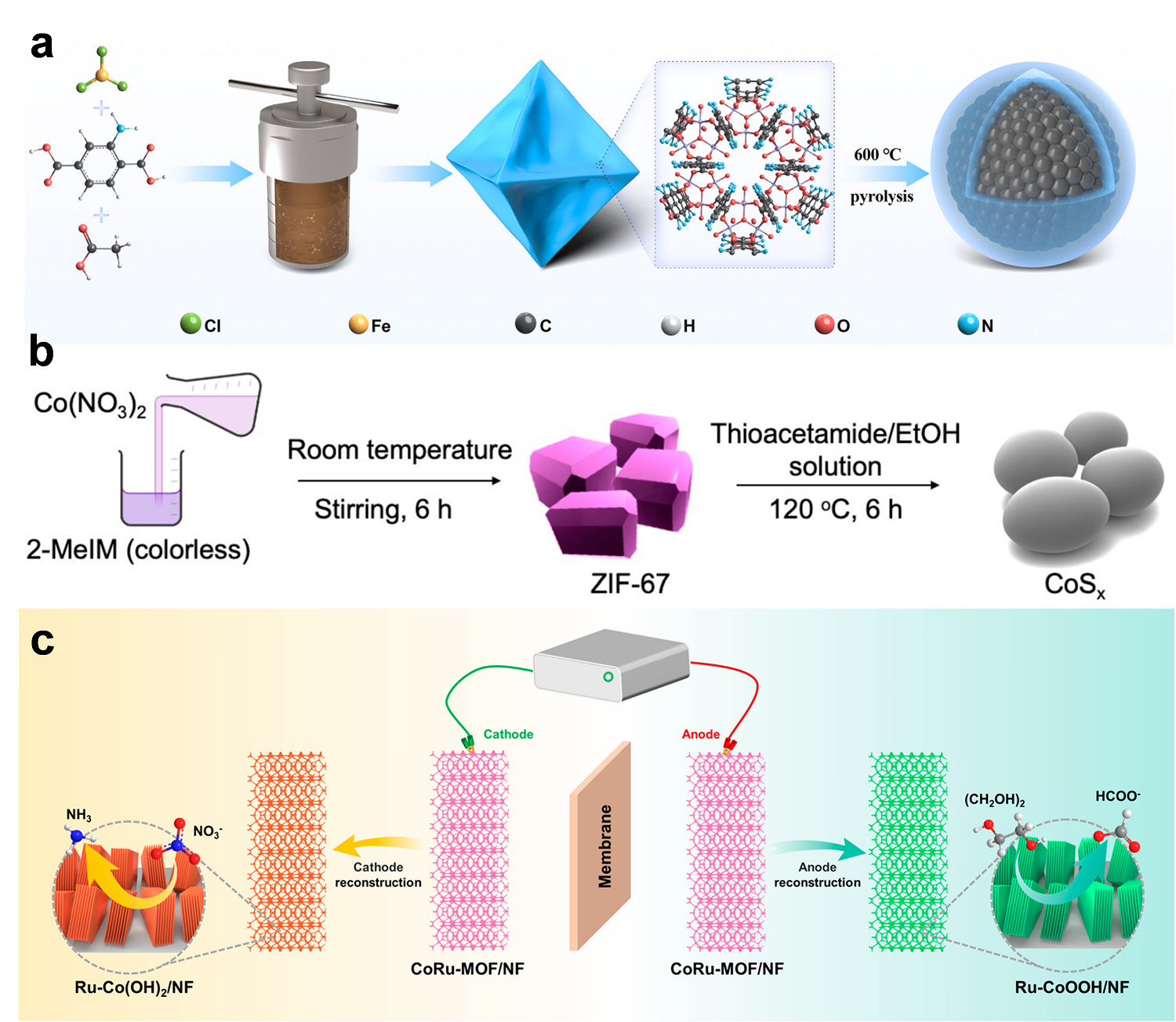
Fig. 9. (a) Synthetic route of Fe3O4@NC-600. Reprinted with permission from Ref. [118]. Copyright 2025, Elsevier. (b) Schematic representation of the synthesis process of cobalt sulfides derived from ZIF-67. Reprinted with permission from Ref. [119]. Copyright 2025, Royal Society of Chemistry. (c) Schematic illustration of the electrocatalytic system for NO3-RR and PET hydrolysate upcycling. Reprinted with permission from Ref. [126]. Copyright 2023, American Chemical Society.

Fig. 10. (a) Schematic illustration of the formation of Cu SACs. (b) The Cu K-edge EXAFS fitting curves of Cu(0.1wt%)/NC. Reprinted with permission from Ref. [131]. Copyright 2023, American Chemical Society. (c) Synthesis and structural characterizations of Fe-N/P-C catalyst. (d) The EDS elemental mappings of Fe-N/P-C. Reprinted with permission from Ref. [133]. Copyright 2023, John Wiley and Sons. (e) Schematic diagram of the EMOFs general synthesis strategy for preparing dual-atom platforms. (f) The 2D atomic resolution map of the Zn-Mn dual-site. Reprinted with permission from Ref. [135]. Copyright 2025, John Wiley and Sons.
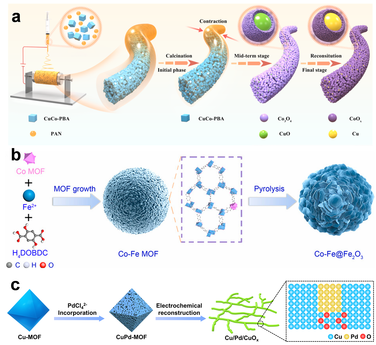
Fig. 11. (a) Schematic of the synthesis process for the rich Cu/CoOx@NFs heterogeneous active electrocatalyst. Reprinted with permission from Ref. [144]. Copyright 2024, Elsevier. (b) Synthetic procedure of Co-Fe@Fe2O3. Reprinted with permission from Ref. [147]. Copyright 2022, National Academy of Sciences. (c) Schematic illustration of the preparation of Cu/Pd/CuOx. Reprinted with permission from Ref. [148]. Copyright 2022, Elsevier.
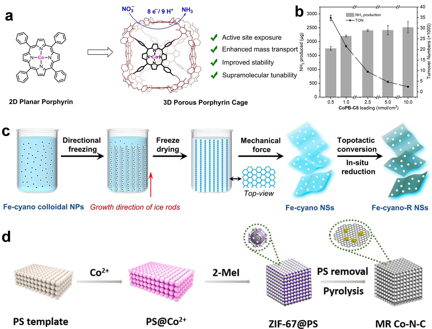
Fig. 12. (a) Supramolecular enhancement of electrochemical NO3-RR catalyzed by embedding 2D molecular cobalt porphyrin into a 3D porous organic cage architecture. (b) NH3 production and TON for various amounts of CoPB-C8 loading at -1.54 V vs. SCE. Reprinted with permission from Ref. [150]. Copyright 2023, John Wiley and Sons. (c) Fe-cyano-R NSs electrocatalysts via directional freezing. Reprinted with permission from Ref. [152]. Copyright 2022, American Chemical Society. (d) Schematic illustration of the synthesis process of MR Co-NC. Reprinted with permission from Ref. [154]. Copyright 2023, Elsevier.
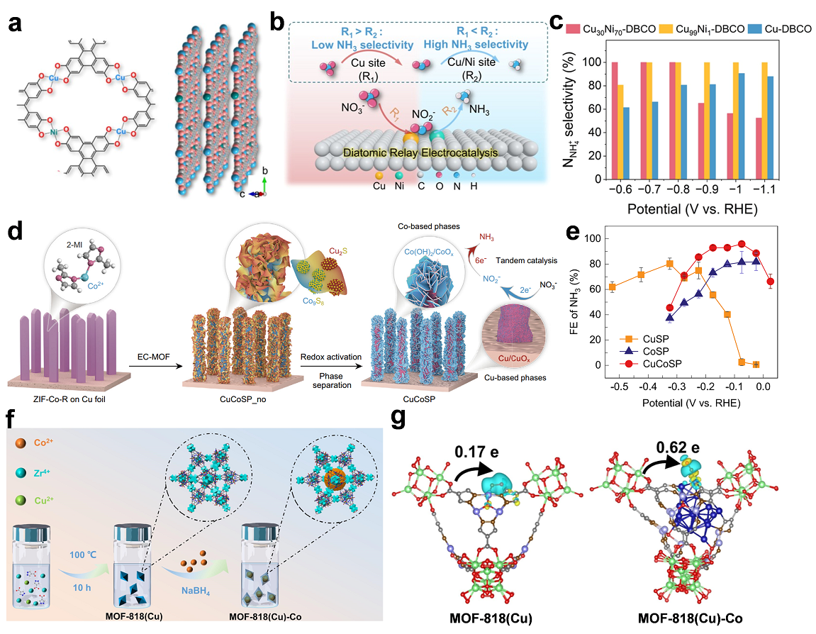
Fig. 13. (a) Top view, and side view of the layer showing the CuO4 and NiO4 nodes. (b) Schematic illustration of NO3-RR selectivity determined by R1 and R2 via the relay electrocatalysis mechanism. (c) NNH4 selectivity over typical samples in Ar-saturated 0.1 mol L‒1 KHCO3 + 0.05 mol L‒1 KNO3 solutions. Reprinted with permission from Ref. [158], Copyright 2025, American Chemical Society. (d) Schematic illustration of the preparation of a Cu/Co-based binary ‘tandem catalyst’. (e) Faradaic efficiencies (FE) for NH3 on CuSP, CoSP and CuCoSP in 0.01 mol L‒1 NO3- and 0.1 mol L‒1 KOH (pH = 13) at various applied potentials. Reprinted with permission from Ref. [159]. Copyright 2022, Springer Nature. (f) Schematic synthesis and structure of MOF-818(Cu)-Co. (g) Charge density difference of *NO adsorbed on MOF-818(Cu) and MOF-818(Cu)-Co. Reprinted with permission from Ref. [160], Copyright 2025, American Chemical Society.
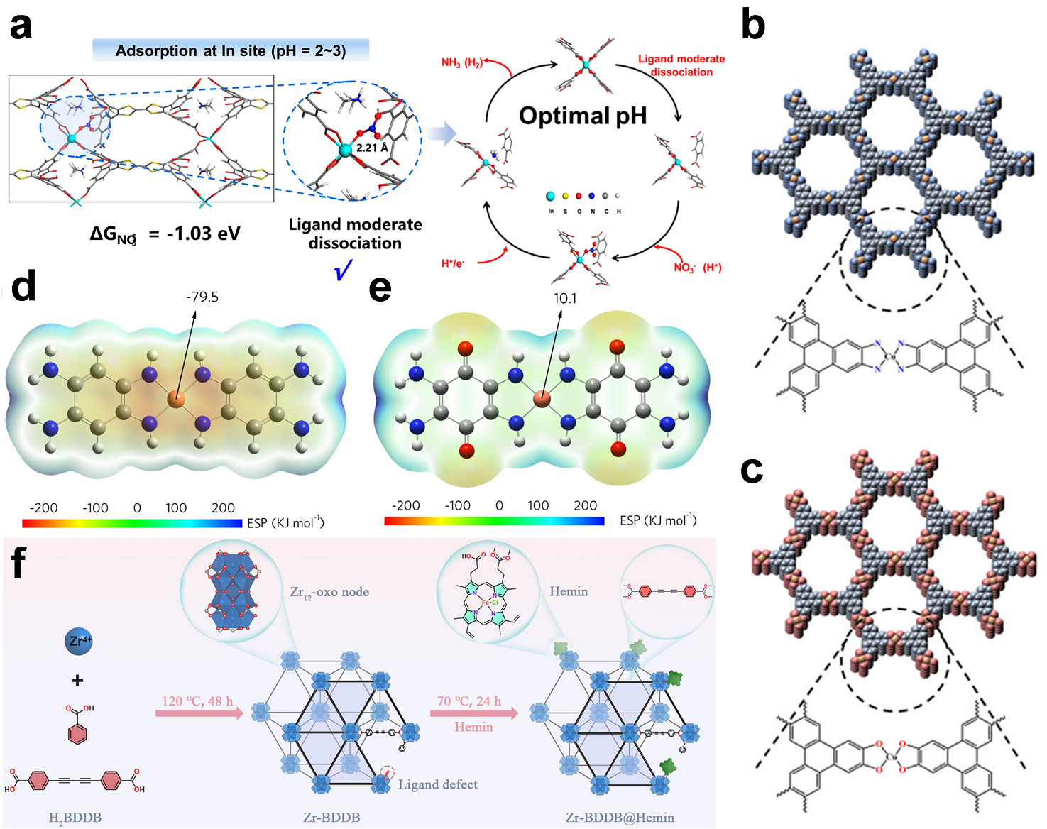
Fig. 14. (a) Schematic diagram of the dynamic dissociation catalytic mechanism for In8 at pH = 2‒3. Reprinted with permission from Ref. [161]. Copyright 2022, American Chemical Society. Crystal structure of Cu3(HITP)2 (b) and Cu3(HHTP)2 (c). Reprinted with permission from Ref. [163]. Copyright 2025, John Wiley and Sons. The ESP for CuBTA (d) and CuTABQ (e). Reprinted with permission from Ref. [165]. Copyright 2023, John Wiley and Sons. (f) Schematic illustration for the preparation of the Zr-BDDB@Hemin. Reprinted with permission from Ref. [168]. Copyright 2025, John Wiley and Sons.
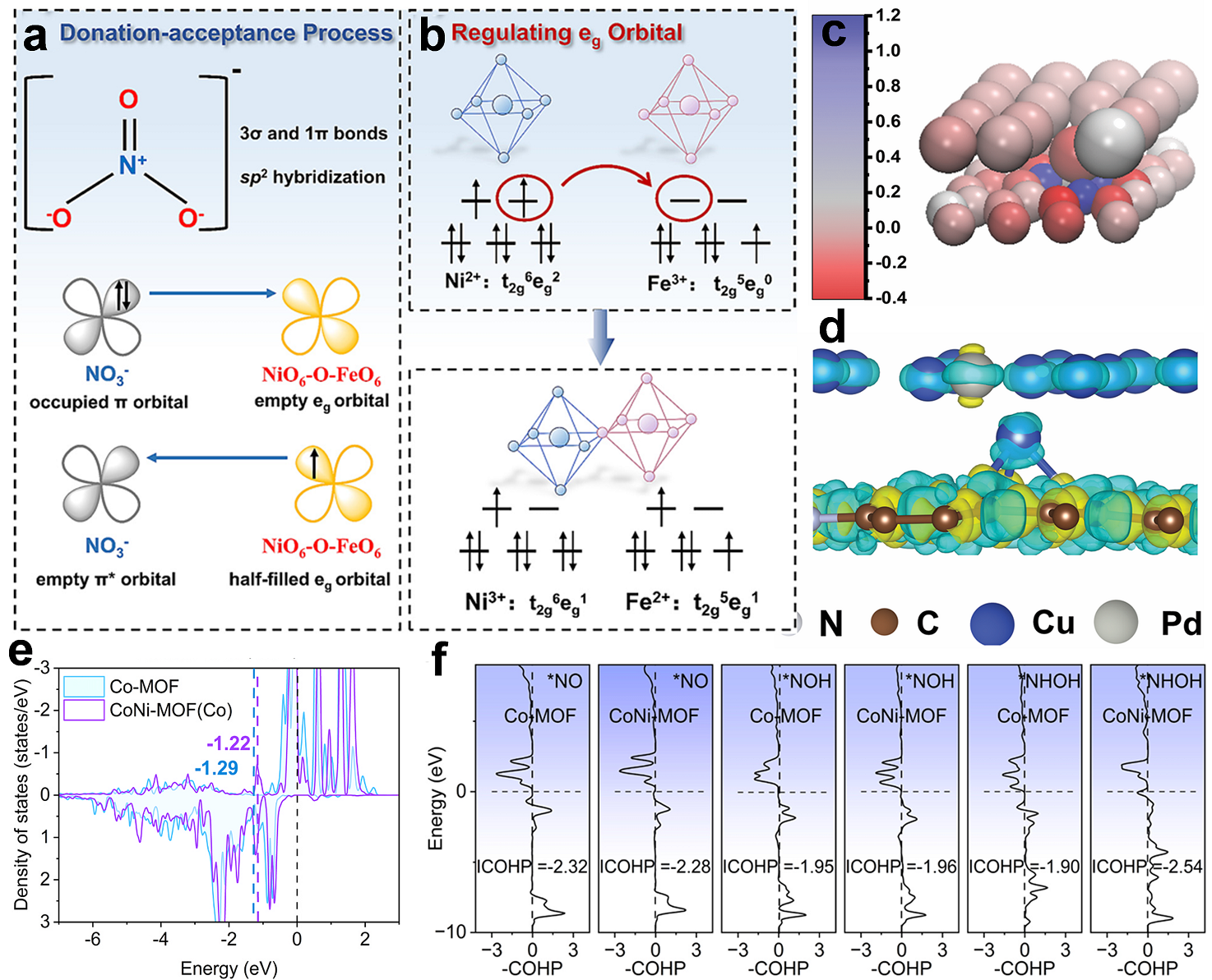
Fig. 15. (a) The structure of nitrate ions and ideal catalytic site following electron back-donation process during N-O activation. (b) Schematic diagram of electron repulsion in eg orbitals. Reprinted with permission from Ref. [169]. Copyright 2025, Elsevier. (c) Bader charge plot of CuPd/CN. (d) Side-view of electron density difference on CuPd/CN. Reprinted with permission from Ref. [170]. Copyright 2022, John Wiley and Sons. (e) PDOS curves of Co 3d in CoNi-MOF and Co-MOF, and the corresponding d-band center values (εd, eV). (f) Projected crystal orbital Hamilton populations for the *NO, *NOH and *NHOH intermediates bonded on the Co site over CoNi-MOF and Co-MOF. Reprinted with permission from Ref. [172]. Copyright 2026, Elsevier.
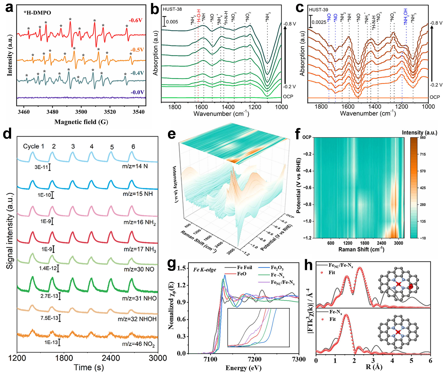
Fig. 16. (a) Generation of *H on Cu-MOF/Co-MOF@NF surface during EPR detection. Reprinted with permission from Ref. [174]. Copyright 2025, American Chemical Society. In-situ FT-IR spectra for HUST-38 (b) and HUST-39 (c). Reprinted with permission from Ref. [89]. Copyright 2025, American Chemical Society. (d) Online DEMS spectra of Fe8Zn1PPc under different applied potentials in NO3-RR. Reprinted with permission from Ref. [94]. Copyright 2025, John Wiley and Sons. (e,f) In-situ Raman plots of Cu-TCPP/Cu2O/CF with a potential change in pH = 7 environment. Reprinted with permission from Ref. [175]. Copyright 2025, American Chemical Society. (g) XANES spectra of the Fe K-edge. (h) Fitting results of the EXAFS spectra at R space. Reprinted with permission from Ref. [141]. Copyright 2025, Elsevier.
|
| [1] | 骆诗剑, 陈浩, 杨宇然, 宋阳, 刘泳铎, 龙道莙, 陈四国, 魏子栋. 氢化物增强的等离子体催化在室温常压下实现超高效率氨合成[J]. 催化学报, 2026, 88(9): 269-278. |
| [2] | 王淼, 沈天宇, 周恒, 杨帅康, 郝风坤, 王超辉, Mohan Kumar, 铁祚庥, 陈双明, 范战西, 金钟. 中性介质中利用原子级精准富羰基金属团簇直接电催化还原硝酸盐合成氨[J]. 催化学报, 2026, 88(9): 259-268. |
| [3] | 郭凤娟, 马春瑶, 黄悦, 杭思彤, 马俊伟, 高洪涛. 远端-交替杂化机制驱动B@Mo2TiC2Tx/MoO2 MXene高效还原N2[J]. 催化学报, 2026, 87(8): 269-281. |
| [4] | 袁欣, 吴林艺, 曹凤莹, 徐乐楚, 王鹏, 石胡琳, 仲淑贤, 刘炼, 莫伟豪, 赵雷洪, 柏嵩. 入射光切换调控空心等离子激元TiO2/AuCu@COF核壳光催化剂的CO2还原产物选择性[J]. 催化学报, 2026, 87(8): 87-99. |
| [5] | 刘均炎, 邵涛, 彭珣, 刘升卫. 配体-缺陷协同催化剂局部增强CO2浓度实现高效低浓度CO2电化学还原[J]. 催化学报, 2026, 86(7): 265-276. |
| [6] | 王超, 冯坤, 唐梁书语, 章伍军, 周沐宇, 李佳璐, 邵天雨, 沈炎宾, 钟俊, 苏韧. 水系电催化氨氧化反应中MOFs活性位点的原位演变[J]. 催化学报, 2026, 86(7): 171-180. |
| [7] | 王翔, 周敏, 廖小彬, 韩旭, 省聪聪, Bes René, Huotari Simo, Arbiol Jordi, Cabot Andreu. MOFs衍生的磷掺杂Co9S8增强氧析出和还原反应: 迈向高性能锌空气电池[J]. 催化学报, 2026, 85(6): 204-215. |
| [8] | 李健, 吴振发, 张欣茹, 颜同安, 罗金, 薛文娟, 吕照临, 黄宏亮, 仲崇立. MOFs中单金属位点到双金属位点的动态配位转变和塑料的级联光重整制CO[J]. 催化学报, 2026, 84(5): 314-323. |
| [9] | 李伊馨, 邱健豪, 夏广路, 刘琪英, 方碧瑶, 刘梦, 陈晨, 姚建峰. 中空管状In2O3修饰氮化碳395 nm光催化木质素C-C键高产率裂解[J]. 催化学报, 2026, 83(4): 209-218. |
| [10] | 彭渲北, 安梦琪, 毛瑞绍, 周岩良, 陈名, 黄东雅, 苏凯琳, 章世勇, 倪军, 王秀云, 江莉龙. 白钨矿型碱金属高铼酸盐负载的钴基催化剂用于高效合成氨[J]. 催化学报, 2026, 83(4): 432-443. |
| [11] | 刘畅, 王梅, 梁向明, 鲁统部. 碳载体上银双原子与银纳米颗粒的耦合用于高效电还原氮气制氨[J]. 催化学报, 2026, 82(3): 135-143. |
| [12] | 王雄, 彭超, 肖永康, 张子烨, 郑慧平, 岳文杰, 田昇, 胡星盛, 邵伟凡, 陈广辉, 王丙昊, 王慧娟, 尹明明, 李锦锌, 李扬, 陈浪, 尹双凤. 通过表面工程提升Bi2WO6-x在选择性C-H键光氧化反应中的催化活性与稳定性[J]. 催化学报, 2026, 81(2): 246-258. |
| [13] | 傅笑言, 栾东, 杨晨宇, 肖建平. 基于电场可调机器学习势函数的氧化物衍生铜催化剂电化学氨合成研究[J]. 催化学报, 2026, 89(10): 410-421. |
| [14] | 费杨, 雷青娟, 范黎明, 胡拖平, 覃其品, 张修堂. 缺陷耐受的二维镧系金属有机框架中有机位点主导催化的CO2增值及密度泛函计算[J]. 催化学报, 2026, 89(10): 353-366. |
| [15] | 肖丽媛, 王振旅, 管景奇. 多核金属有机框架材料在电催化中的研究进展[J]. 催化学报, 2026, 80(1): 59-91. |
| 阅读次数 | ||||||
|
全文 |
|
|||||
|
摘要 |
|
|||||


