
Chinese Journal of Catalysis ›› 2026, Vol. 89: 142-176.DOI: 10.1016/S1872-2067(26)65055-3
• Review • Previous Articles Next Articles
Zixian Guoa, Youhang Hea, Mingfei Yua, Liuyi Lia,*( ), Jinhong Bib,*(), Yan Yua, Ling Wuc,*()
Received:2026-02-01
Accepted:2026-02-27
Online:2026-10-18
Published:2026-09-01
Contact:
*E-mail:lyli@fzu.edu.cn(L. Li),bijinhong@fzu.edu.cn(J. Bi),wuling@fzu.edu.cn(L. Wu).
About author:Liuyi Li (College of Materials Science and Engineering, Fuzhou University) received his M.S. degree in Organic Chemistry from Huazhong University of Science and Technology in 2007 and his Ph.D. degree in Environmental Chemistry from Fuzhou University in 2017. He has been working at Fuzhou University since 2017, and was promoted to a full professor in 2021. His research interests currently focus on the rational design of covalent organic frameworks for photocatalysis, with emphasis on CO2 reduction and water splittingSupported by:Zixian Guo, Youhang He, Mingfei Yu, Liuyi Li, Jinhong Bi, Yan Yu, Ling Wu. Multiscale engineering of COFs toward practical photocatalysis: From heterojunction design to membrane fabrication[J]. Chinese Journal of Catalysis, 2026, 89: 142-176.
Add to citation manager EndNote|Ris|BibTeX
URL: https://www.cjcatal.com/EN/10.1016/S1872-2067(26)65055-3
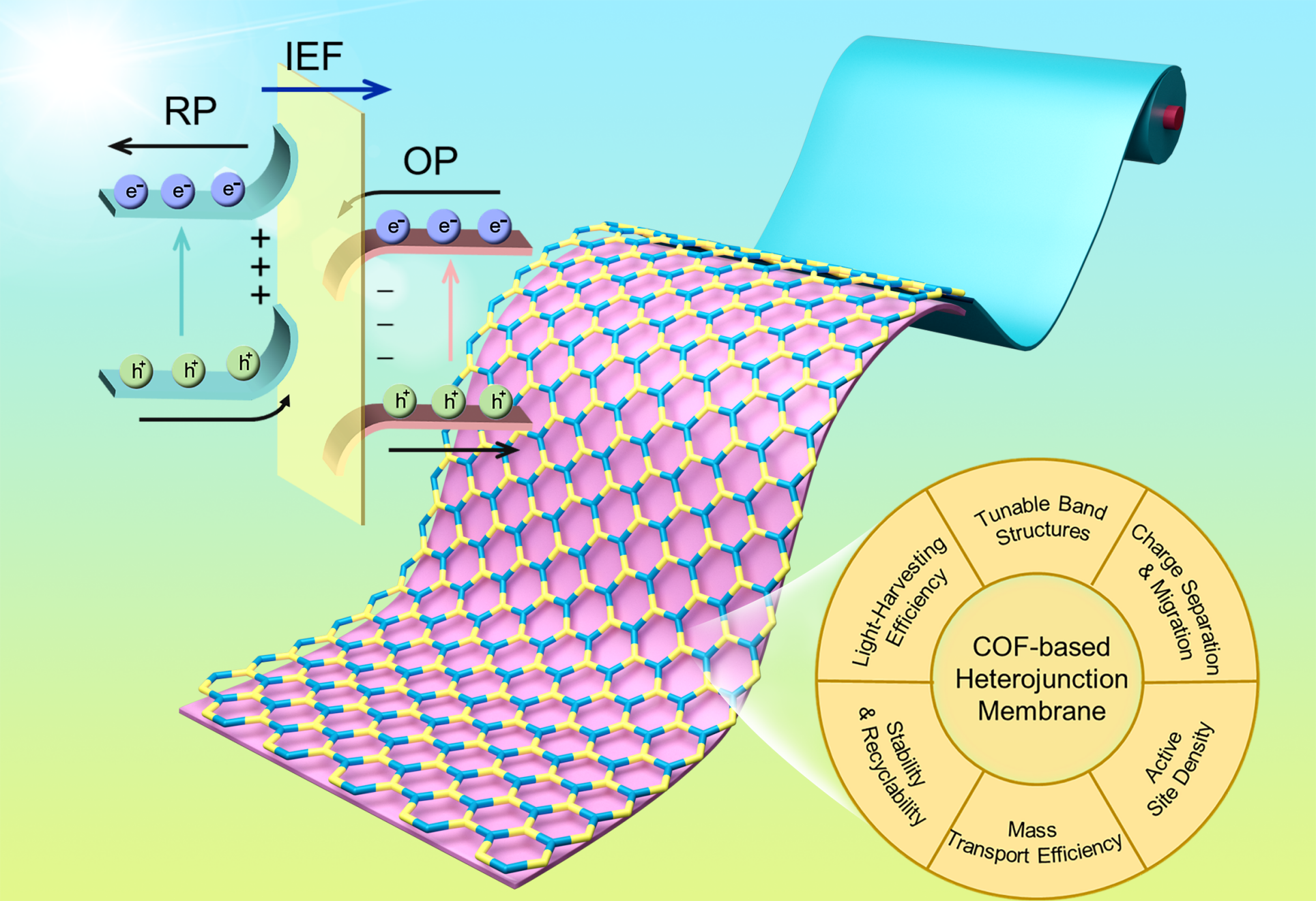
Fig. 1. Schematic representation of COF-based heterojunction membranes for photocatalysis.
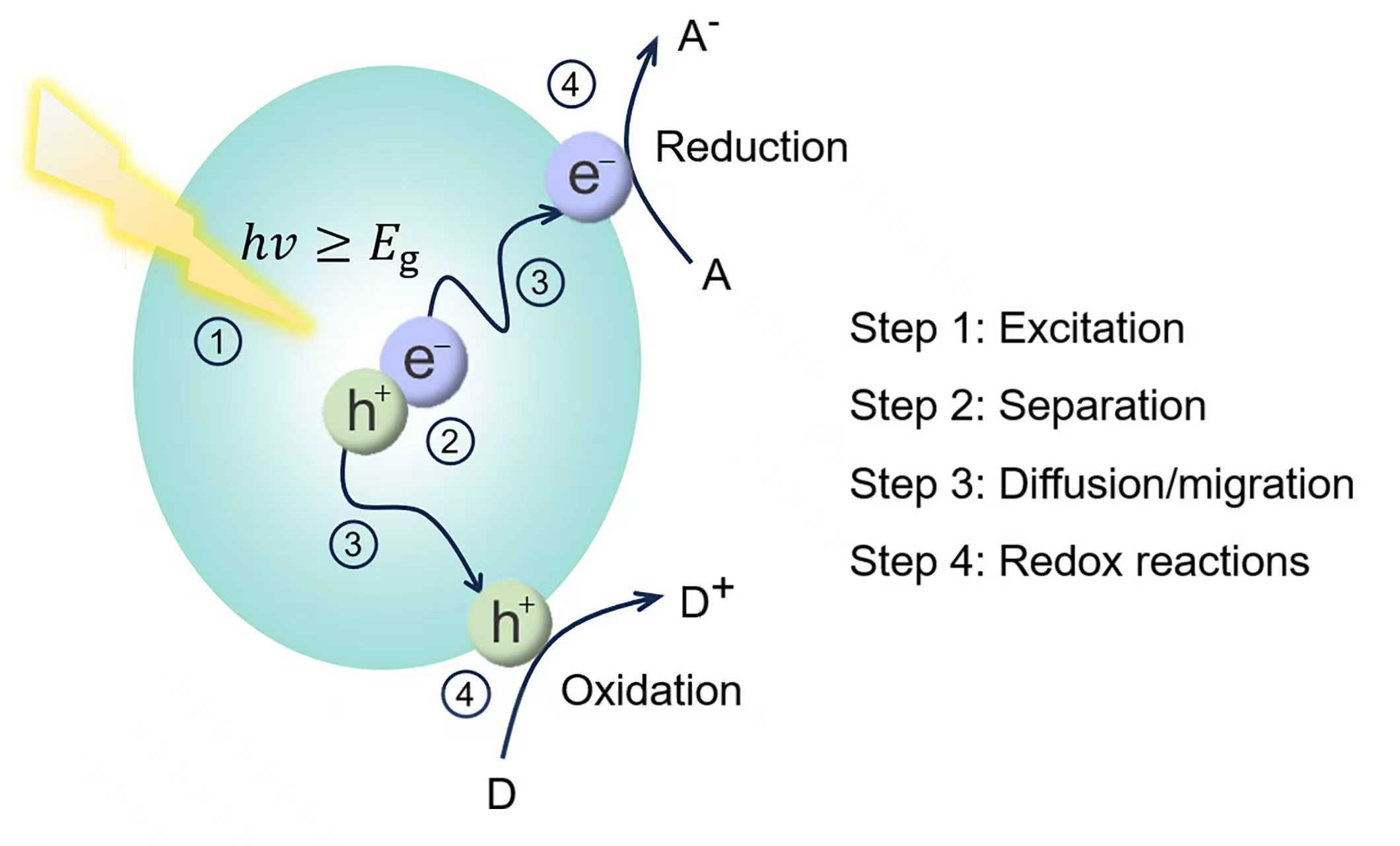
Fig. 2. Reaction mechanism of semiconductor photocatalysis.
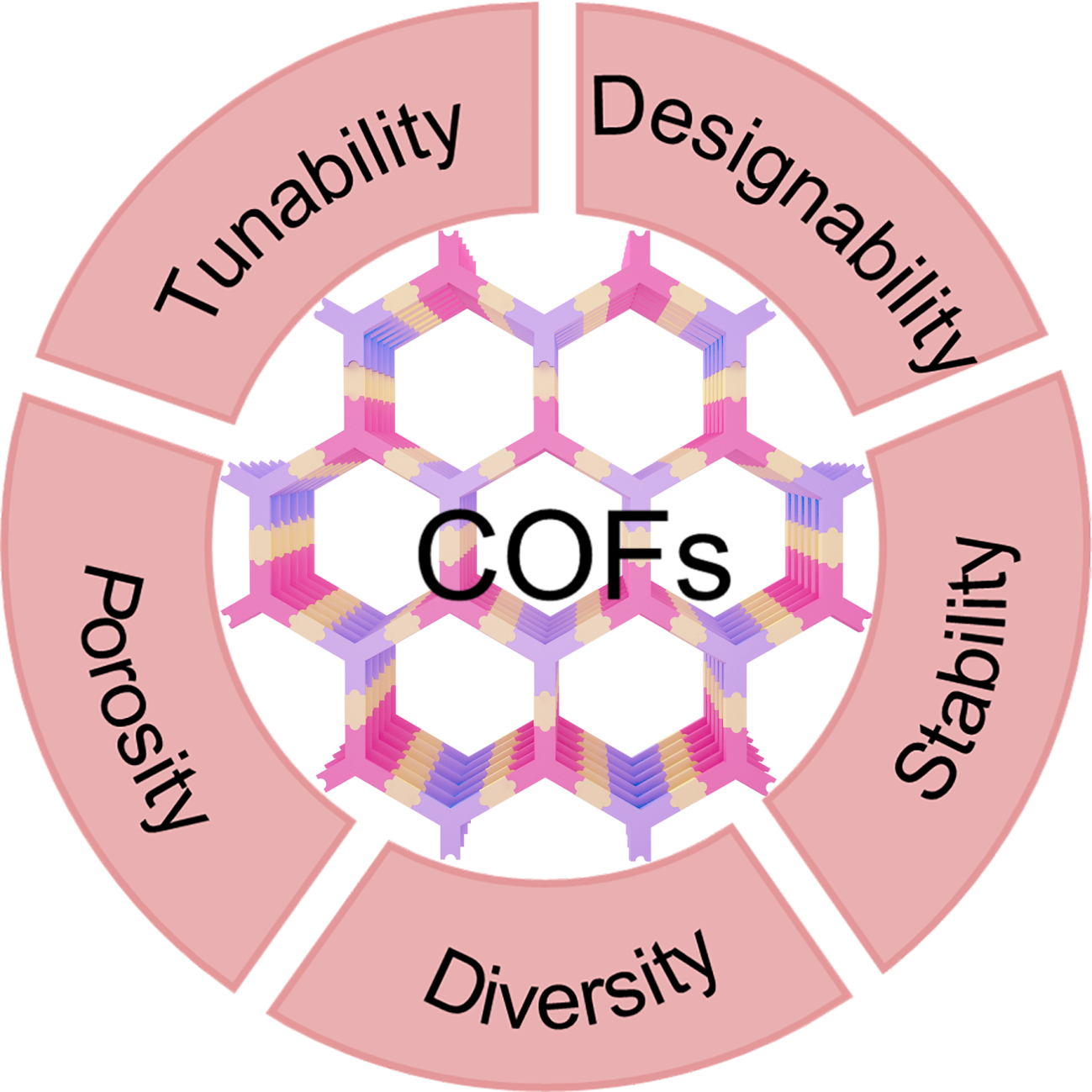
Fig. 3. Advantages of COFs as photocatalysts.
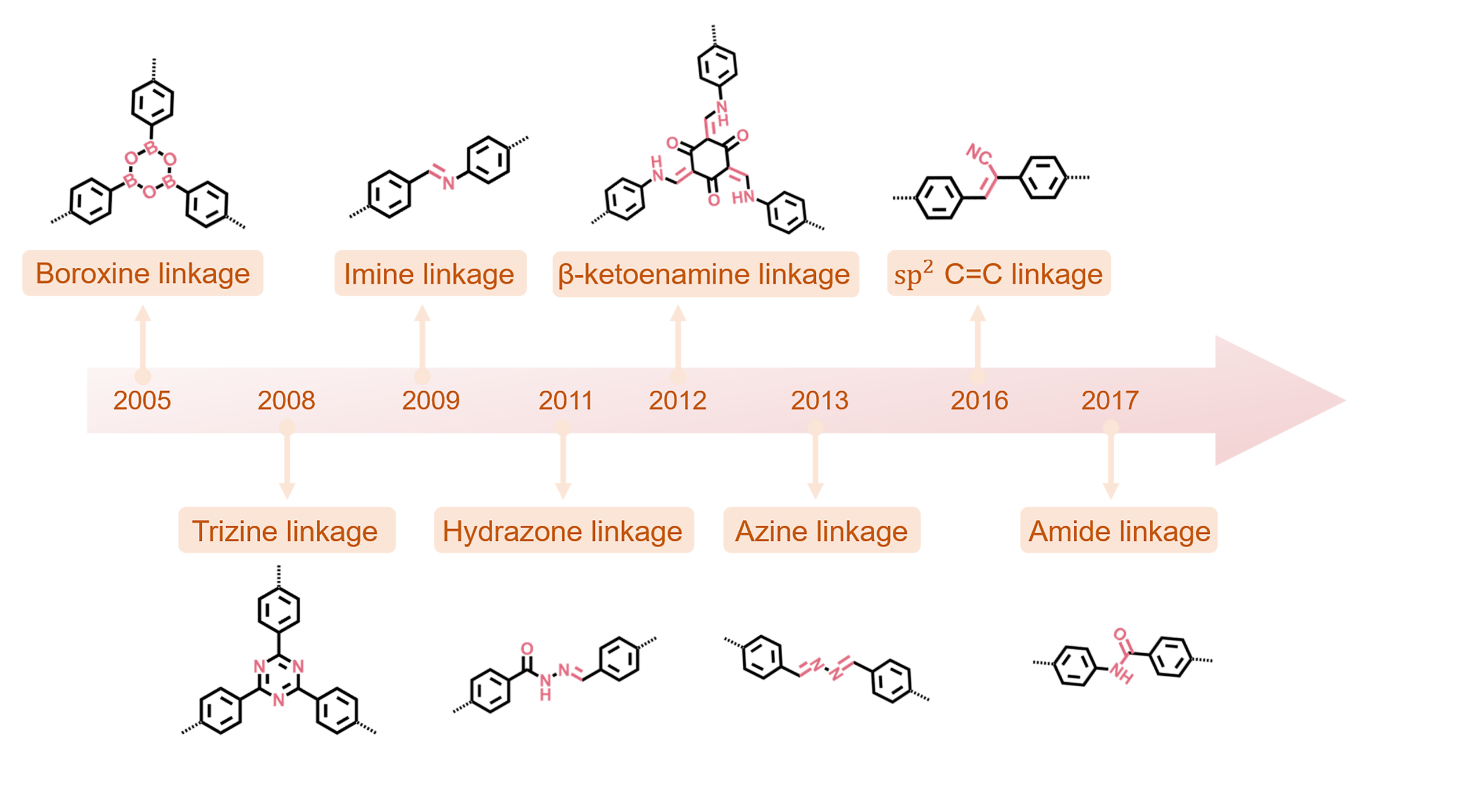
Fig. 4. Timeline of major linkages in photoactive covalent organic framework synthesis. The amide linkage is a representative stable motif.
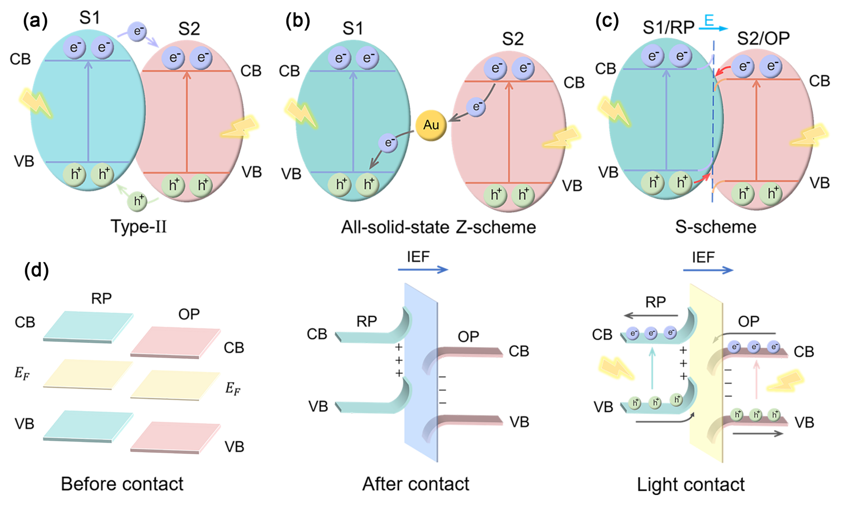
Fig. 5. (a) Type-II heterojunction. (b) Z-scheme heterojunction. (c) S-scheme heterojunction. (d) Charge transfer processes in S-scheme heterojunction.
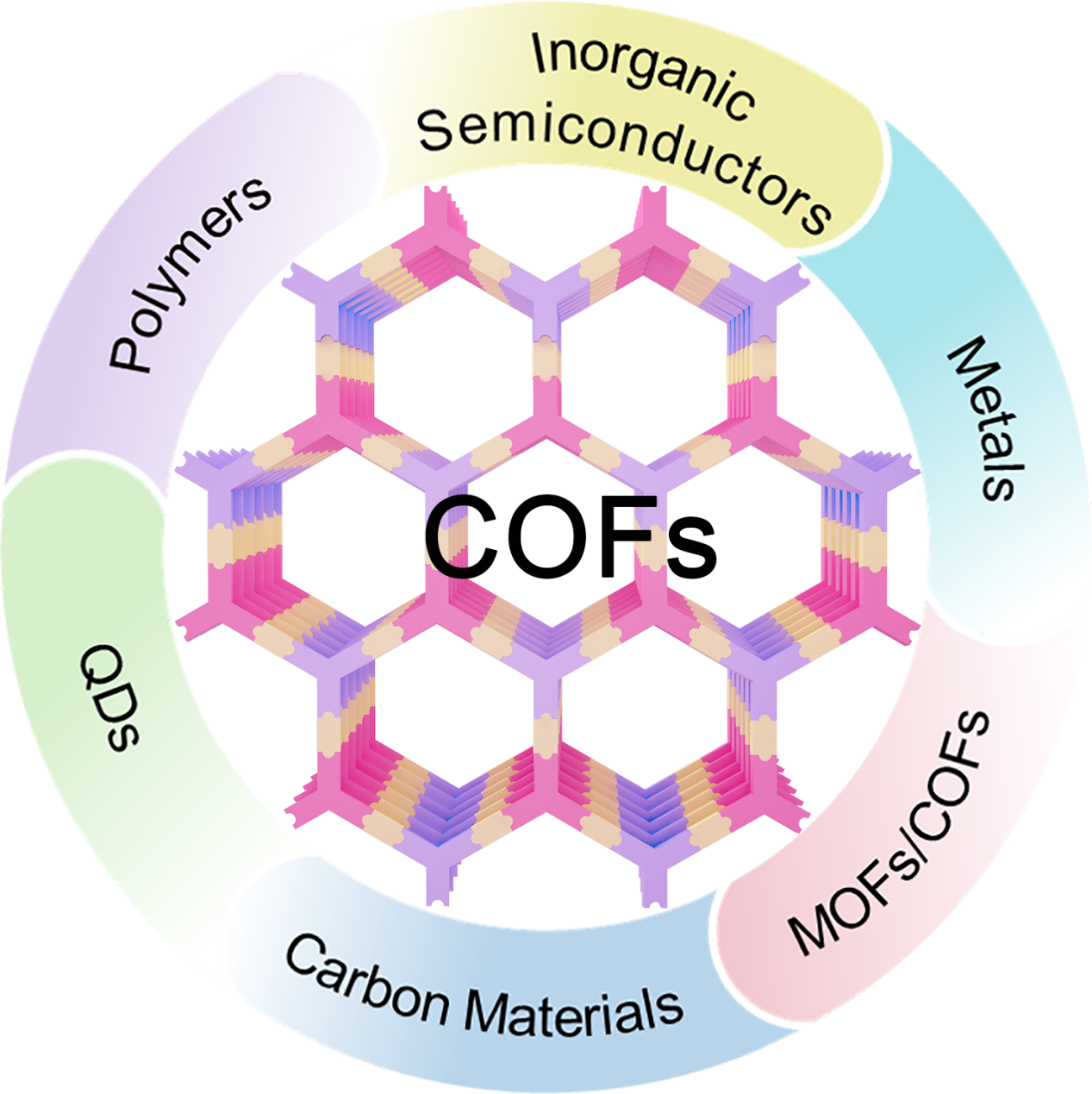
Fig. 6. Fabrication of COF-based photocatalysts via combination with different materials.
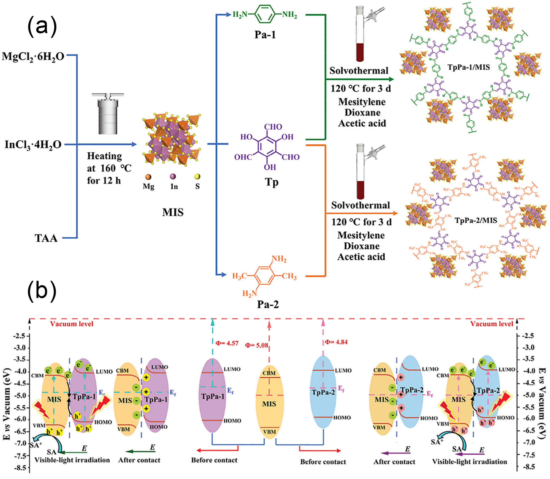
Fig. 7. (a) Schematic illustration of the TpPa-1/MIS and TpPa-2/MIS heterojunction preparation. (b) S-scheme charge migration in TpPa/MIS heterojunctions. Reprinted with permission from Ref. [69]. Copyright 2025, John Wiley and Sons.

Fig. 8. (a) Schematic of the synthesis for PtNPs@CTF-1. (b) TEM image of PtNPs@CTF-1 (scale bar: 10 nm) showing the lattice fringes of PtNPs. (c) The reaction mechanism for PtNPs@CTF-1. Reprinted with permission from Ref. [70]. Copyright 2024, Springer Nature. (d) Proposed photocatalytic CO2-to-CO mechanism over Fe SAS/Tr-COFs. (e) Top-view charge density difference of Fe SAS/Tr-COFs. Skyblue, electron accumulation; yellow, depletion. Reprinted with permission from Ref. [74]. Copyright 2022, American Chemical Society.
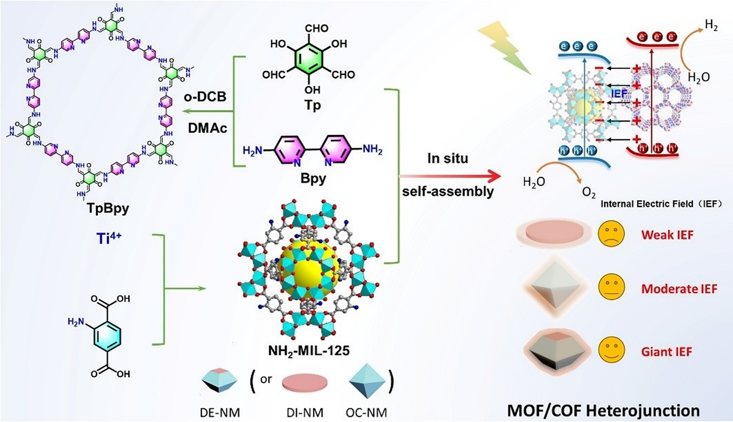
Fig. 9. Schematic of the synthesis for the NH2-MIL-125(Ti)/TpBpy-COF hybrid material. Reprinted with permission from Ref. [79]. Copyright 2025, John Wiley and Sons.
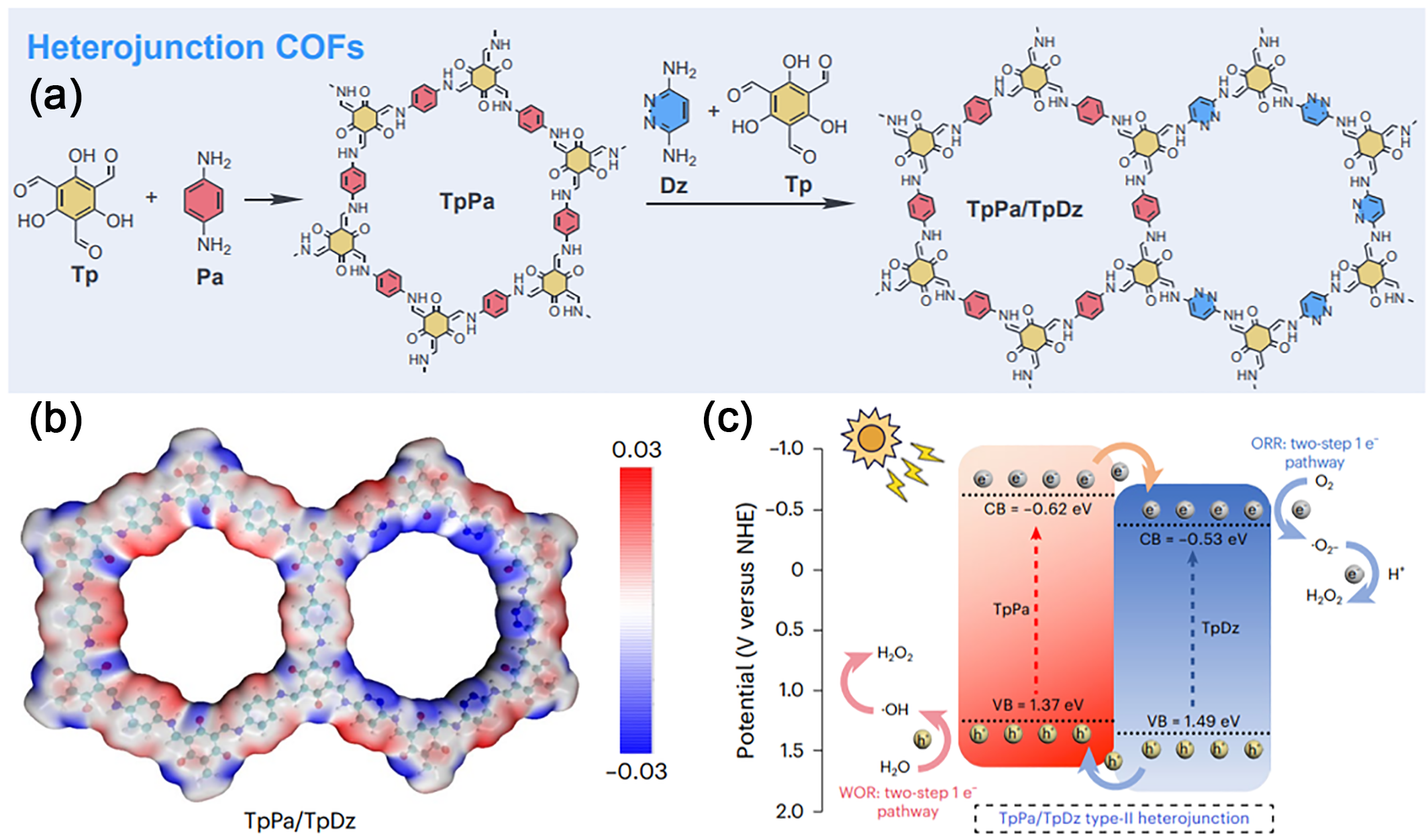
Fig. 10. (a) Structure and Synthesis of the TpPa/TpDz Heterojunction. (b) Electrostatic potential surfaces (EPSs) of TpPa/TpDz. (c) Mechanism for H2O2 photoproduction on the TpPa/TpDz heterojunction. Reprinted with permission from Ref. [82]. Copyright 2025, Springer Nature.
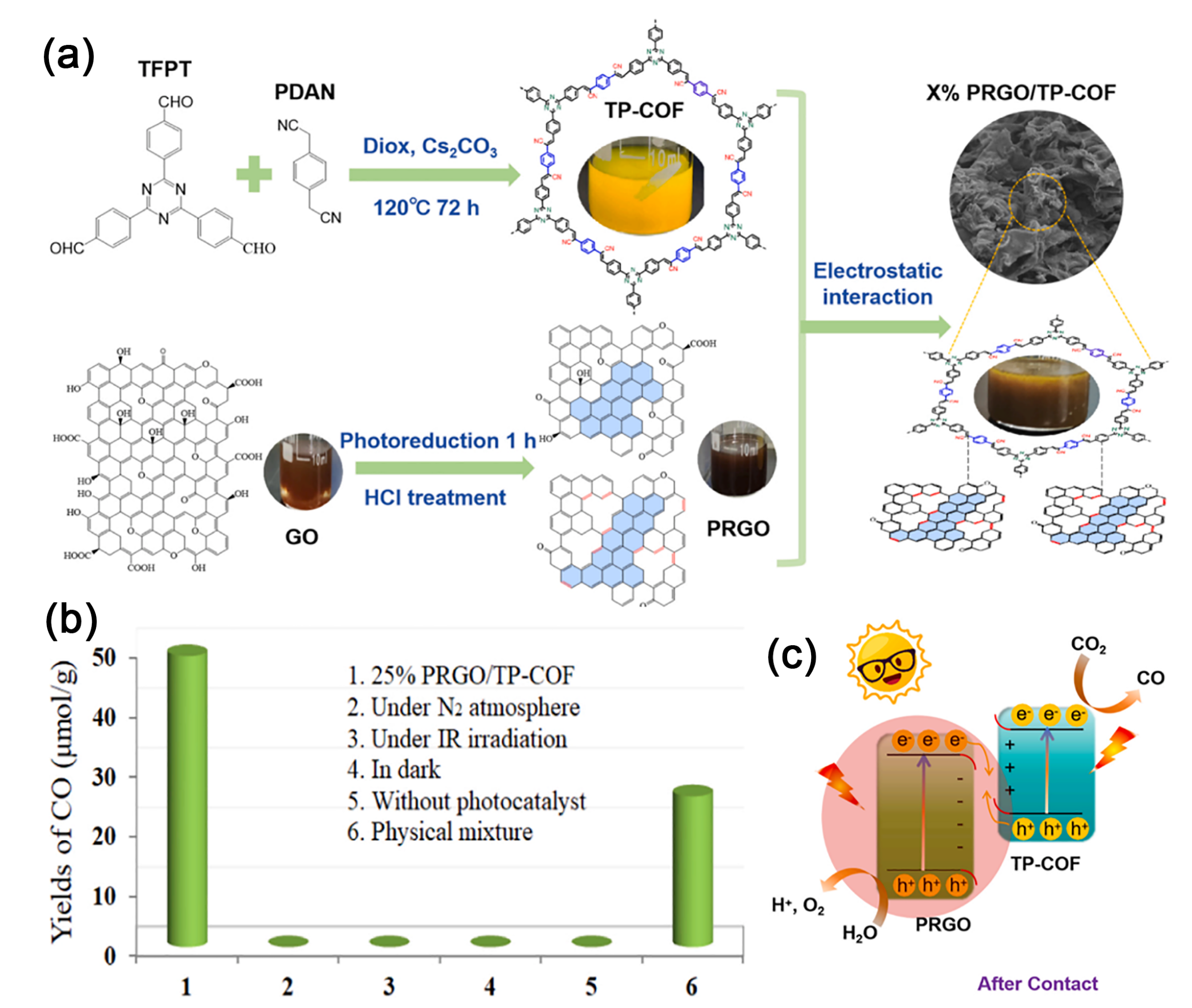
Fig. 11. (a) Synthesis of PRGO/TP-COF Nanocomposites. (b) CO Yield Performance of 25% PRGO/TP-COF under Varied Conditions. (c) Photocatalytic CO2 Reduction by 25% PRGO/TP-COF Nanocomposites. Reprinted with permission from Ref. [88]. Copyright 2024, Elsevier.

Fig. 12. (a) Schematic illustration of the synthesis process for TT-COF/ZCS composites. High-resolution XPS spectra of N 1s (b) and Zn 2p (c) for TT-COF, ZCS, and TZ-40 before and after illumination. (d) Decay pathways of photogenerated electrons in TZ-40. Reprinted with permission from Ref. [90]. Copyright 2024, John Wiley and Sons. (e) Schematic synthesis and porous cage structure of the COF/ZnSe composite. Surface potential of (f) COF and (g) COF/ZnSe-1 under dark and 365 nm light illumination. (h) Schematic relaxation pathways of photogenerated charge carriers in the COF/ZnSe composite. Reprinted with permission from Ref. [93]. Copyright 2025, John Wiley and Sons.
| Photocatalyst | Type | Synthesis method | Application | Light source | Activity | Ref. |
|---|---|---|---|---|---|---|
| COF@CeO2 | Z | in-situ reaction | CO2 reduction | 300 W λ > 420 nm | 66.2 μmol g-1 | [ |
| JUC-X@ZIS | Z | in-situ growth | H2 generation | 10 W LED λ = 420 nm | 9.46 mmol g-1 h-1 | [ |
| TiO2/T-COF | Z | in-situ growth | CO2 reduction | PLS-SXE 300 | 2.3 μmol h-1 | [ |
| Ag3PO4/COF | Z | in-situ synthesis | RhB degradation | 300 W λ > 420 nm | 96.7% (40 min) | [ |
| ZnIn2S4/Tp-Tta COF | S | in-situ growth | organic transformations | LED 80 W | 12.1 mmol g-1 h-1 | [ |
| MAPbBr3/COF | S | self-assembly | organic transformations | blue LED | PTD, 100% | [ |
| Rh-COF@COF | S | in-situ growth | organic transformations | 300 W λ ≥ 420 nm | 2.6 mmol g-1 h-1 | [ |
| W18O49@TpPa-H | S | in-situ growth | organic transformations | 10 W 420 nm LED | 99% within 4 h | [ |
| TpPa-COF/2D g-C3N4 | S | in-situ growth | H2 generation | λ ≥ 420 nm | 17600 μmol g-1 h-1 | [ |
| TB-1 | S | solvothermal | H2O2 production | λ > 420 nm | 723 μmol g-1 h-1 | [ |
| sp2c-COF/Py-NH2-COF | S | solvothermal | purification | 300 W Xe lamp | TC, 94.8%, 1.5 h | [ |
| ZnO/TpPa-Cl | S | in-situ growth | H2O2 production | 300 W Xe lamp | 2443 μmol g-1 h-1 | [ |
| CdS/BiVO4@T-COF | S | self-assembly | CO2 reduction | 300 W 420 ~780 nm | 183.8 μmol g-1 h-1 | [ |
| PRGO/TP-COF | S | self-assembly | CO2 reduction | 300 W λ > 400 nm | 9.76 μmol g-1 h-1 | [ |
| TpMA/In2S3 | S | hydrothermal | H2O2 production | 300 W λ ≥ 420 nm | 311.07 μmol L-1 | [ |
| TiO2/COF | S | in-situ growth | H2O2 production | 300 W 350 ~780 nm | 740 μmol L-1 h-1 | [ |
| g-C3N4(NH)/COF | S | solvothermal | CO2 reduction | 300 W λ > 400 nm | 11.25 μmol h-1 | [ |
| TiO2/TpPa-Cl | S | solvothermal | H2O2 production | 300W 350 ~800 nm | 2082.6 μmol g-1 h-1 | [ |
| COF/Ni-ZIF-8 | S | in-situ growth | CO2 reduction | 300 W λ > 420 nm | 28.7 μmol g-1 h-1 (CH₄) | [ |
| ZnO/COF | S | in-situ growth | H2O2 generation | 365 nm | AQY = 5% | [ |
| BiOBr/COF | S | hydrothermal | degradation | 300 W | 94.6% (120 min) | [ |
| 20N-COF/BOB | S | in-situ growth | TC degradation | 300 W λ > 420 nm | 81.2% (120 min) | [ |
| TiO2/COF | S | in-situ growth | H2 generation | 300 W λ > 380 nm | 3962 μmol g-1 h-1 | [ |
| TpPa-1/MIS-5% | S | in-situ growth | H2 generation | 300 W λ ≥ 420 nm | 13.16 mmol g-1 h-1 | [ |
| CZS-FOCTF | S | hydrothermal | H2 generation | 300 W λ > 420 nm | 247.62 mmol g-1 h-1 | [ |
| MOS2/COF | Type-II | hydrothermal | TC degradation | 300W AM 1.5 | 98% (30 min) | [ |
| CuPor-Ph-COF/g-C3N4 | Type-II | in-situ synthesis | RhB degradation | 300 W λ > 400 nm | 94.5% (90 min) | [ |
| Au2-COF | Schottky junction | deposition | nitrate reduction | 300 W AM 1.5 | 382.48 μmol g-1 h-1 | [ |
Table 1 COF-based heterojunction photocatalysts for various photocatalytic applications.
| Photocatalyst | Type | Synthesis method | Application | Light source | Activity | Ref. |
|---|---|---|---|---|---|---|
| COF@CeO2 | Z | in-situ reaction | CO2 reduction | 300 W λ > 420 nm | 66.2 μmol g-1 | [ |
| JUC-X@ZIS | Z | in-situ growth | H2 generation | 10 W LED λ = 420 nm | 9.46 mmol g-1 h-1 | [ |
| TiO2/T-COF | Z | in-situ growth | CO2 reduction | PLS-SXE 300 | 2.3 μmol h-1 | [ |
| Ag3PO4/COF | Z | in-situ synthesis | RhB degradation | 300 W λ > 420 nm | 96.7% (40 min) | [ |
| ZnIn2S4/Tp-Tta COF | S | in-situ growth | organic transformations | LED 80 W | 12.1 mmol g-1 h-1 | [ |
| MAPbBr3/COF | S | self-assembly | organic transformations | blue LED | PTD, 100% | [ |
| Rh-COF@COF | S | in-situ growth | organic transformations | 300 W λ ≥ 420 nm | 2.6 mmol g-1 h-1 | [ |
| W18O49@TpPa-H | S | in-situ growth | organic transformations | 10 W 420 nm LED | 99% within 4 h | [ |
| TpPa-COF/2D g-C3N4 | S | in-situ growth | H2 generation | λ ≥ 420 nm | 17600 μmol g-1 h-1 | [ |
| TB-1 | S | solvothermal | H2O2 production | λ > 420 nm | 723 μmol g-1 h-1 | [ |
| sp2c-COF/Py-NH2-COF | S | solvothermal | purification | 300 W Xe lamp | TC, 94.8%, 1.5 h | [ |
| ZnO/TpPa-Cl | S | in-situ growth | H2O2 production | 300 W Xe lamp | 2443 μmol g-1 h-1 | [ |
| CdS/BiVO4@T-COF | S | self-assembly | CO2 reduction | 300 W 420 ~780 nm | 183.8 μmol g-1 h-1 | [ |
| PRGO/TP-COF | S | self-assembly | CO2 reduction | 300 W λ > 400 nm | 9.76 μmol g-1 h-1 | [ |
| TpMA/In2S3 | S | hydrothermal | H2O2 production | 300 W λ ≥ 420 nm | 311.07 μmol L-1 | [ |
| TiO2/COF | S | in-situ growth | H2O2 production | 300 W 350 ~780 nm | 740 μmol L-1 h-1 | [ |
| g-C3N4(NH)/COF | S | solvothermal | CO2 reduction | 300 W λ > 400 nm | 11.25 μmol h-1 | [ |
| TiO2/TpPa-Cl | S | solvothermal | H2O2 production | 300W 350 ~800 nm | 2082.6 μmol g-1 h-1 | [ |
| COF/Ni-ZIF-8 | S | in-situ growth | CO2 reduction | 300 W λ > 420 nm | 28.7 μmol g-1 h-1 (CH₄) | [ |
| ZnO/COF | S | in-situ growth | H2O2 generation | 365 nm | AQY = 5% | [ |
| BiOBr/COF | S | hydrothermal | degradation | 300 W | 94.6% (120 min) | [ |
| 20N-COF/BOB | S | in-situ growth | TC degradation | 300 W λ > 420 nm | 81.2% (120 min) | [ |
| TiO2/COF | S | in-situ growth | H2 generation | 300 W λ > 380 nm | 3962 μmol g-1 h-1 | [ |
| TpPa-1/MIS-5% | S | in-situ growth | H2 generation | 300 W λ ≥ 420 nm | 13.16 mmol g-1 h-1 | [ |
| CZS-FOCTF | S | hydrothermal | H2 generation | 300 W λ > 420 nm | 247.62 mmol g-1 h-1 | [ |
| MOS2/COF | Type-II | hydrothermal | TC degradation | 300W AM 1.5 | 98% (30 min) | [ |
| CuPor-Ph-COF/g-C3N4 | Type-II | in-situ synthesis | RhB degradation | 300 W λ > 400 nm | 94.5% (90 min) | [ |
| Au2-COF | Schottky junction | deposition | nitrate reduction | 300 W AM 1.5 | 382.48 μmol g-1 h-1 | [ |
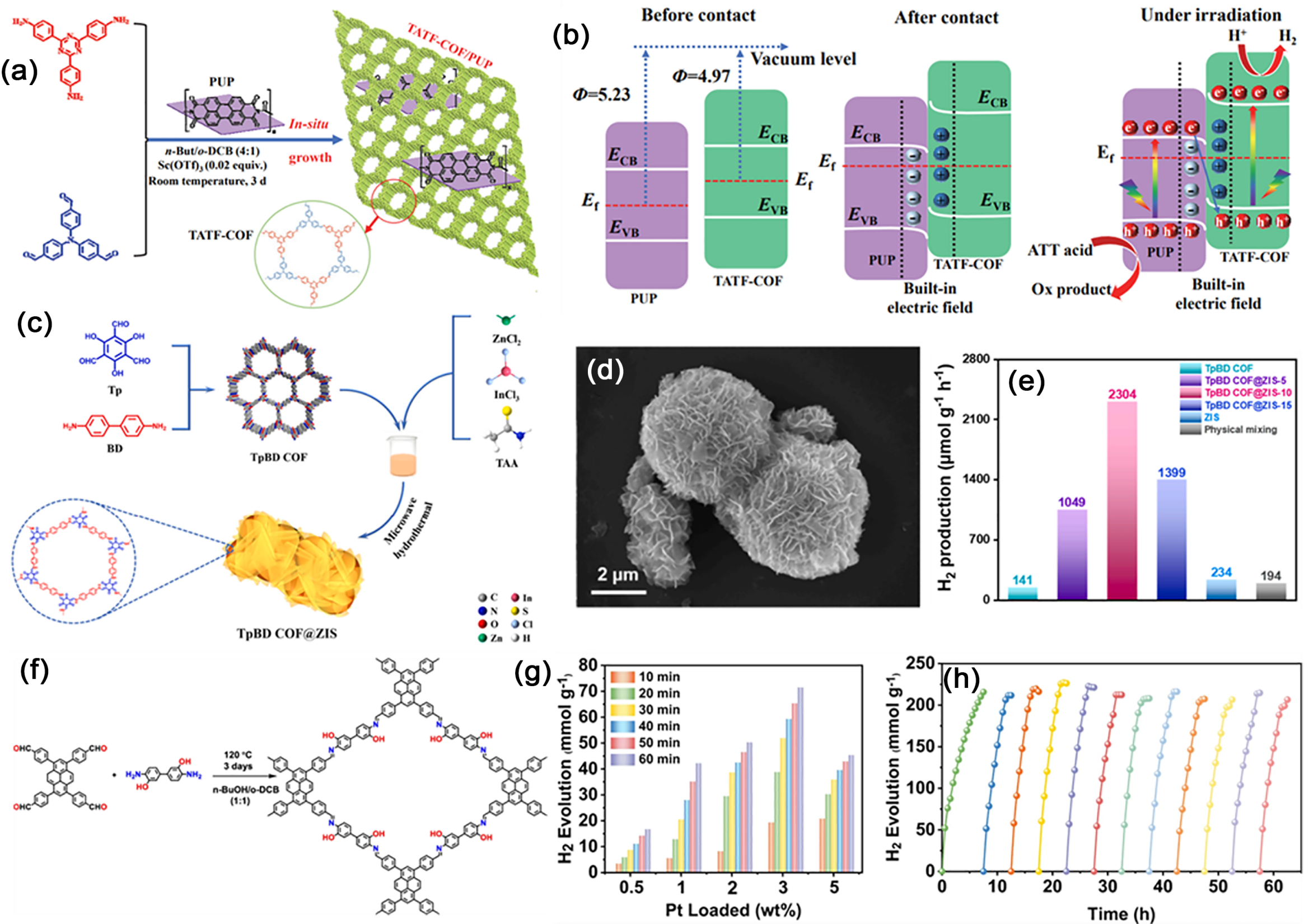
Fig. 13. (a) Synthesis schematic of the TATF COF/PUP heterojunction. (b) Proposed S-scheme mechanism in TATF-COF/PUP heterojunction. Reprinted with permission from Ref. [125]. Copyright 2022, Elsevier. (c) Synthesis of the TpBD COF@ZIS heterojunction. (d) SEM images. (e) H2 production rate versus ZIS loading in TpBD COF@ZIS. Reprinted with permission from Ref. [128]. Copyright 2023, Elsevier. (f) Synthesis process and structure of PY-DHBD-COF. (g) H2 evolution versus time for PY-DHBD-COF with varying Pt loadings. (h) Longterm H2 production for 3 wt% Pt loaded PY-DHBD-COF. Reprinted with permission from Ref. [129]. Copyright 2022, Springer Nature.
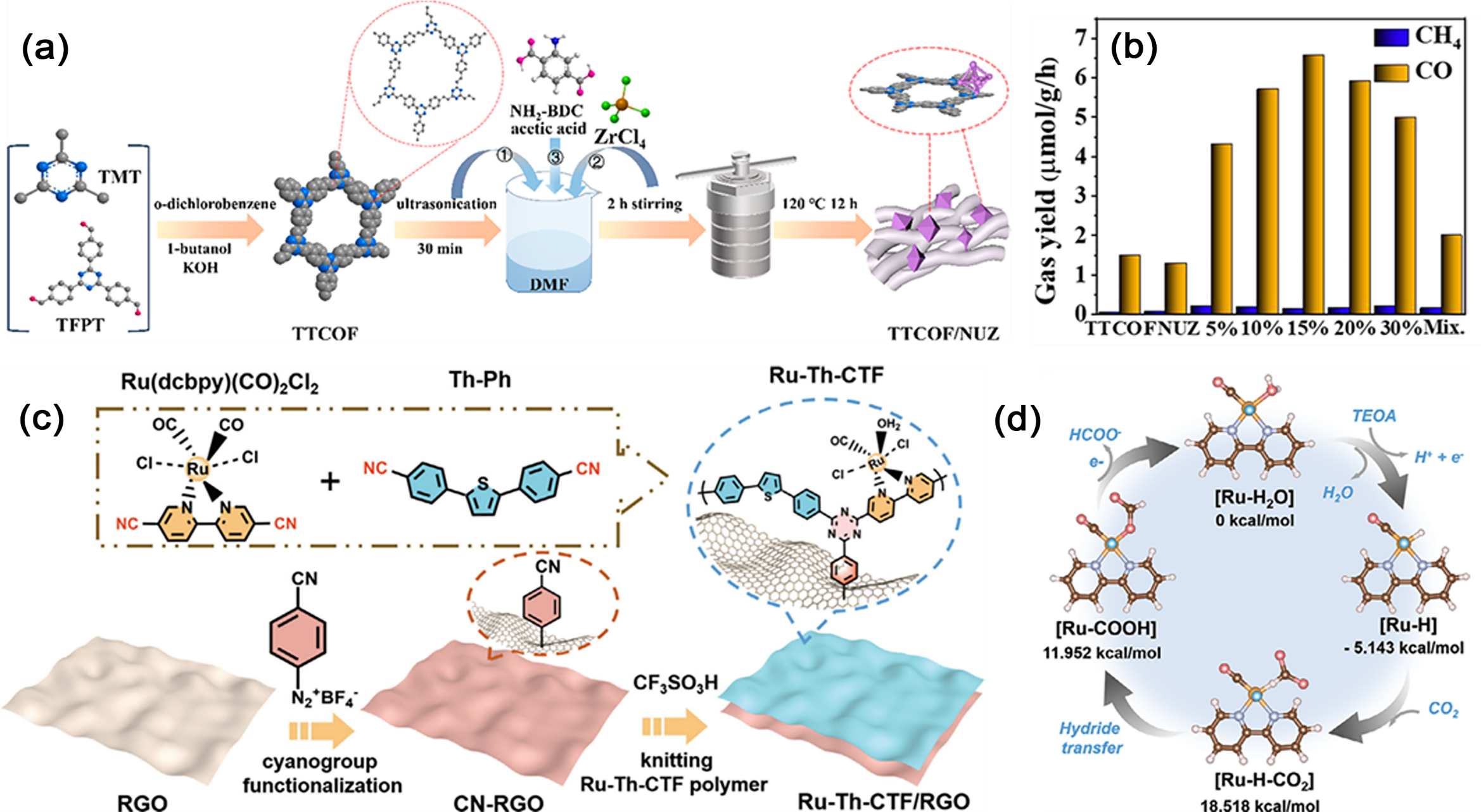
Fig. 14. (a) Preparation of TTCOF/NUZ composites with varying TTCOF contents. (b) Photocatalytic CO2 conversion rates of TTCOF, NUZ, and x% TTCOF/NUZ (x = 5, 10, 15, 20, 30). Reprinted with permission from Ref. [134]. Copyright 2022, American Chemical Society. (c) Schematic illustration of the synthetic route toward Ru-Th-CTF/RGO. (d) Photocatalytic pathway and free energy changes for CO2 reduction to HCOO- on the Ru center. Reprinted with permission from Ref. [135]. Copyright 2023, John Wiley and Sons.
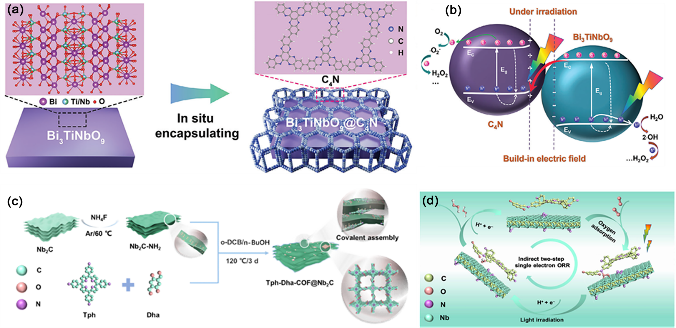
Fig. 15. (a) Schematic of the fabrication process for the Bi3TiNbO9@C4N heterojunction. (b) Schematic of H2O2 photosynthesis coupled with photoinduced charge transfer in the Bi3TiNbO9@C4N heterojunction. Reprinted with permission from Ref. [139]. Copyright 2025, John Wiley and Sons. (c) Schematic illustration of the preparation of the Tph-Dha-COF@Nb2C heterojunction. (d) Proposed 2e- ORR mechanism of H2O2 generation on Tph-Dha-COF@Nb2C. Reprinted with permission from Ref. [140]. Copyright, 2025, Elsevier.

Fig. 16. (a) Schematic synthesis process of the TiO2/TD COF composite. (b) TEM image of the TiO2/TD COF composite. (c) RhB photodegradation over different photocatalyst. (d) Schematic for the decay pathways of photogenerated electrons in TiO2/TD COF heterojunction. Reprinted with permission from Ref. [144]. Copyright, 2025, Elsevier. (e) Synthetic routes and the photo of MT-COF-Au. (f) Possible degradation pathways of BTA in the photocatalytic system. Reprinted with permission from Ref. [146]. Copyright 2024, Elsevier.
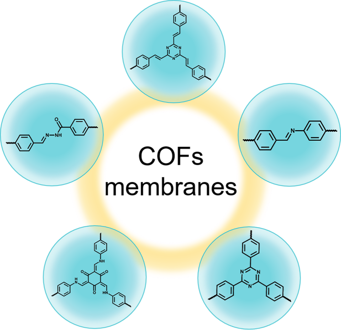
Fig. 17. Representative linkages involved in the COF membranes formation.
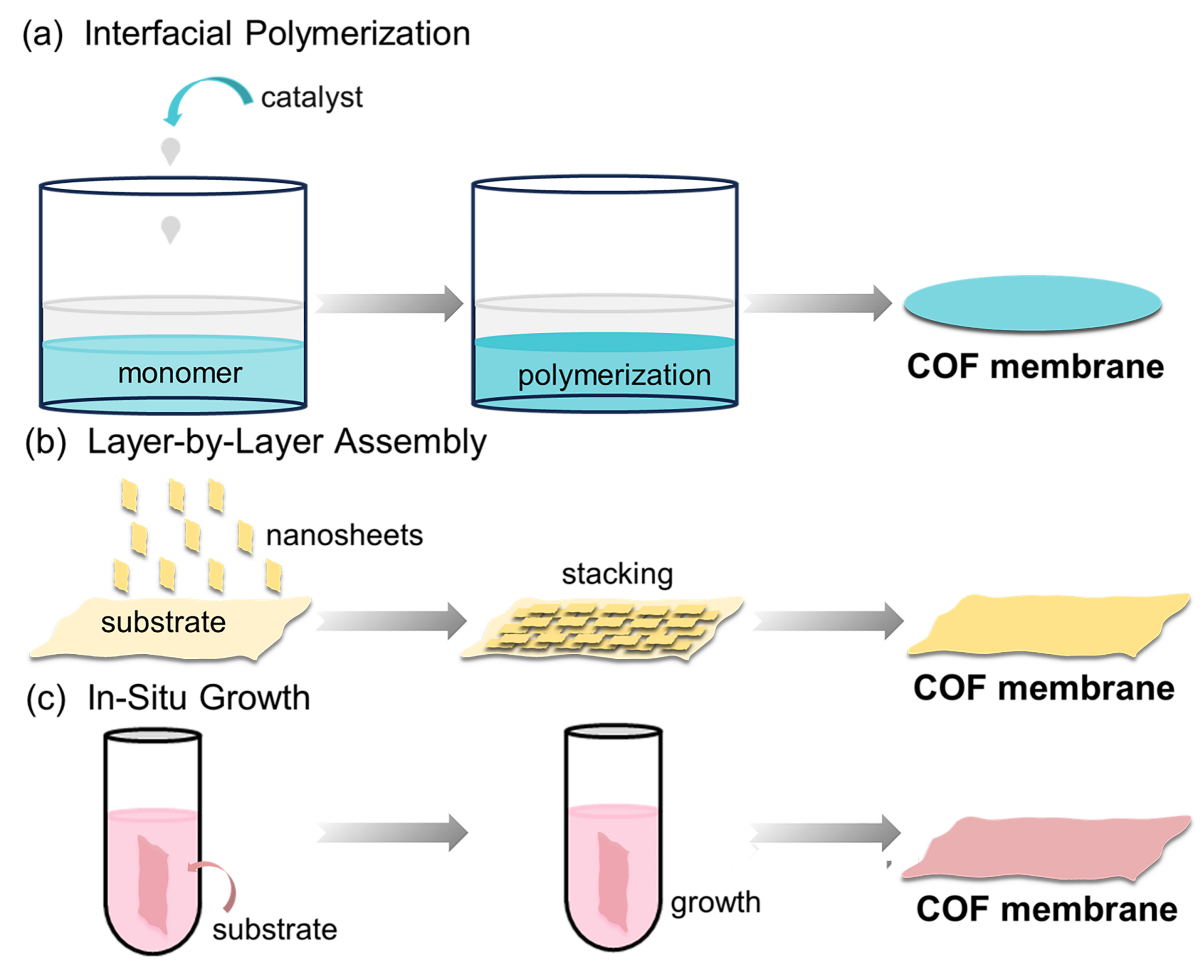
Fig. 18. Schematic illustration of common strategies for COF membrane fabrication. (a) Interfacial polymerization; (b) layer-by-layer assembly; (c) in-situ growth approach.
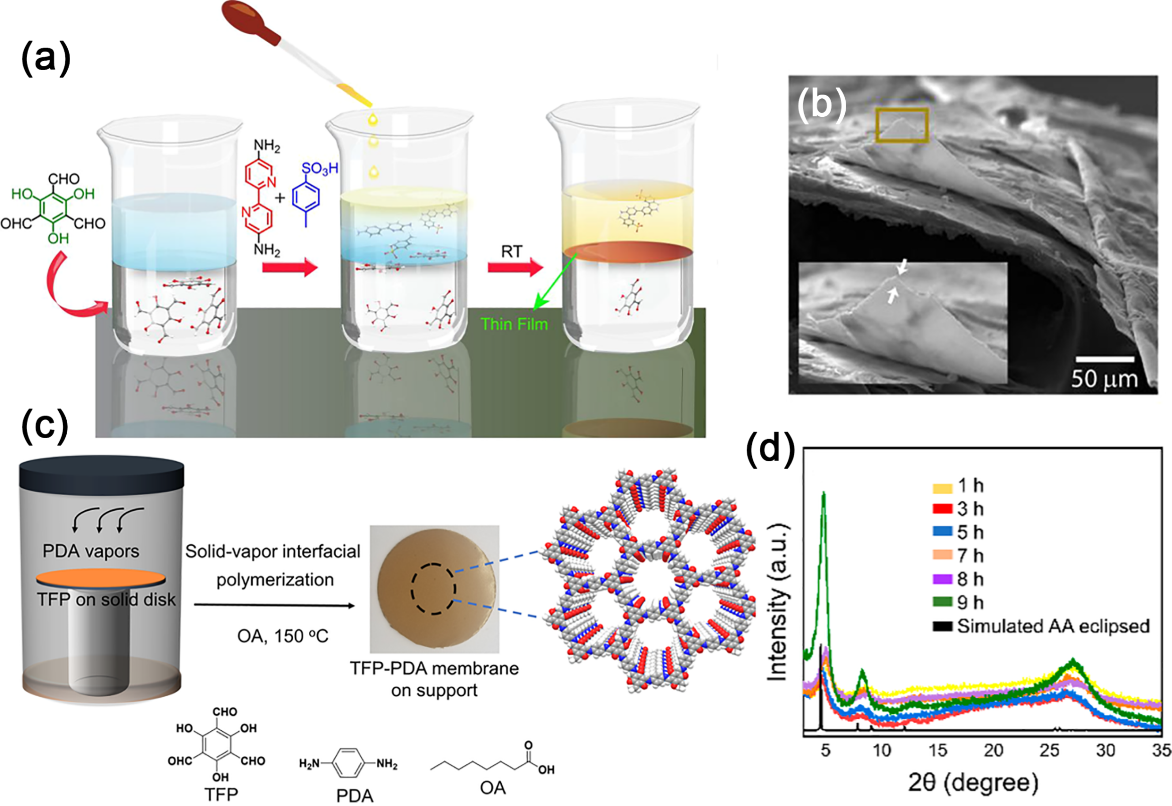
Fig. 19. (a) Synthesis scheme of COF thin membranes. (b) SEM images. Reprinted with permission from Ref. [159]. Copyright 2017, American Chemical Society. (c) Schematic of the COF membrane formation via vapor-solid interfacial reaction. (d) Evolution of XRD patterns of the TFP-PDA membranes over time. Reprinted with permission from Ref. [164]. Copyright 2020, American Chemical Society.
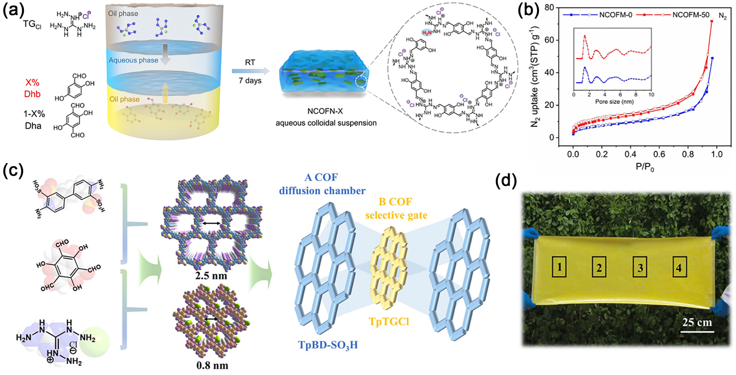
Fig. 20. (a) Synthesis of NCOFN Nanosheets via Oil-Water-Oil Triphase Method. (b) N2 Isotherms (77 K) and Pore Size Distributions of NCOFM-0 and NCOFM-50 Freestanding Membranes. Reprinted with permission from Ref. [169]. Copyright 2022, John Wiley and Sons. (c) Schematic of COF assembly forming an hourglass-shaped channel. (d) Digital photograph of the ultra-large-area membrane. Reprinted with permission from Ref. [171]. Copyright 2025, John Wiley and Sons.
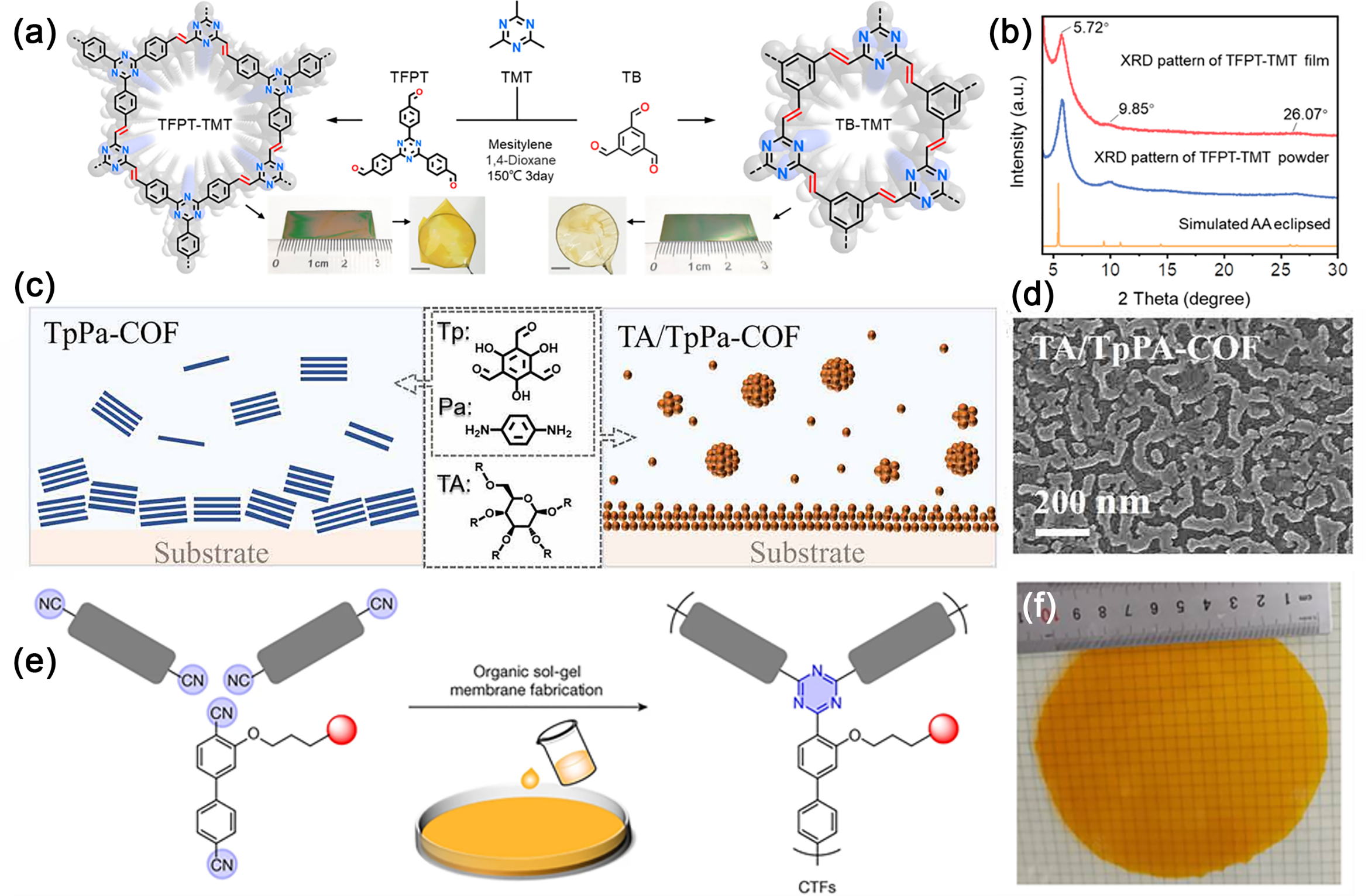
Fig. 21. (a) Synthetic scheme for TB-TMT and TFPT-TMT membranes. (b) XRD patterns of TFPT-TMT membrane, powder, and structure stimulation. Reprinted with permission from Ref. [175]. Copyright 2023, American Chemical Society (c) Surface-initiated growth of a TA/TpPa-COF membrane via TA-mediated nucleation. (d) SEM image of the TA/TpPa-COF membrane surface. Reprinted with permission from Ref. [179]. Copyright 2021, John Wiley and Sons. (e) Schematic structure of CTF membranes. (f) shows a free-standing CTF membrane with a diameter of over 10 cm. Reprinted with permission from Ref. [183]. Copyright 2023, Springer Nature.
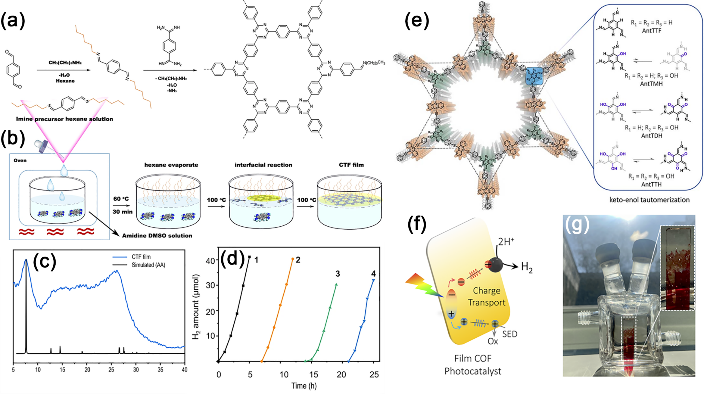
Fig. 22. (a) Reaction steps. (b) Synthetic procedure for the fabrication of CTF membrane on DMSO surface assisted by imine precursor. (c) PXRD of collected CTF membrane and its simulated XRD pattern with AA stacking. (d) Photocatalytic HER performance of membrane on glass in four cycles under visible light (> 420 nm). Reprinted with permission from Ref. [185]. Copyright 2021, Springer Nature. (e) Chemical structures of anthracene-based COFs. (f) Proposed photocatalytic HER mechanism in COF membranes. (g) AntTTH membrane under diffuse sunlight inside a photocatalytic reactor. Reprinted with permission from Ref. [187]. Copyright 2024, Royal Society of Chemistry.
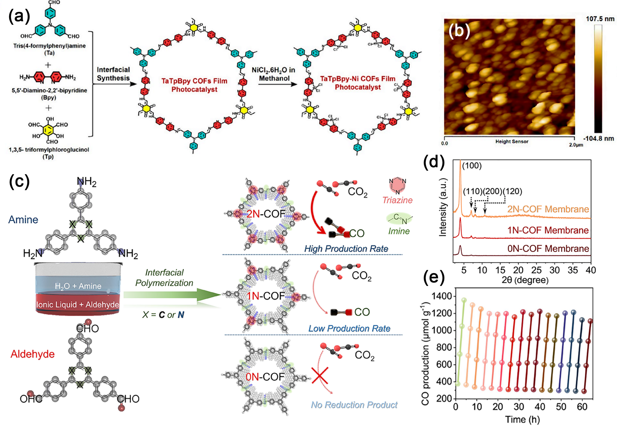
Fig. 23. (a) Synthesis Scheme of a TaTpBpy-Ni COFs membrane Photocatalyst. (b) AFM images of the TaTpBpy-Ni@PET. Reprinted with permission from Ref. [190]. Copyright 2024, American Chemical Society. (c) Schematic illustration for the synthesis of 0N-COF, 1NCOF, and 2N-COF membranes at the ionic liquid-H2O interface. (d) Experimental XRD patterns of the COF membranes. (e) Time courses of the photocatalytic activity and durability based on the 2N-COF membrane. Reprinted with permission from Ref. [191]. Copyright 2023, American Chemical Society.
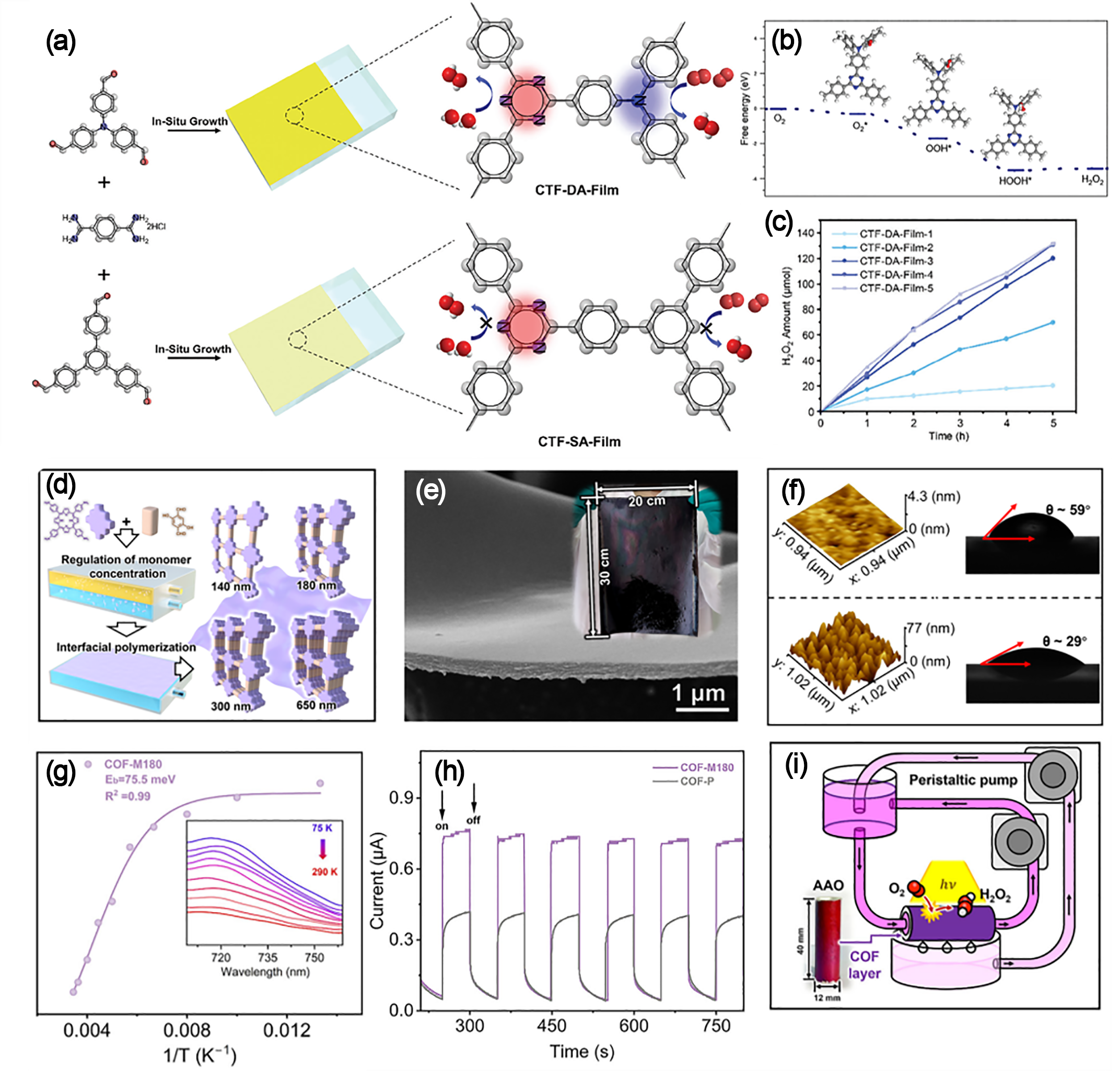
Fig. 24. (a) Schematic formation of CTF-DA-Film and CTF-SA-Film via in-situ polymerization on glass. (b) Free energy of the photocatalytic H2O2 production process over the CTF-DA segment. (c) Production rate of CTF-DA-Film after 1-5 growth cycles. Reprinted with permission from Ref. [194]. Copyright 2024, John Wiley and Sons. (d) Schematic of interfacial polymerization for thickness-tunable COF membrane fabrication. (e) SEM image of COF-M180. Inset: photo of the large-area membrane (20 cm × 30 cm) on PAN. (f) Characterization of surface roughness (AFM) and wettability (contact angle) on both sides of the membrane. (g) Temperature-dependent integrated PL intensity for COF-M180. (h) Photocurrent response measurements of COF-M180 and COF-P. (i) Schematic illustration of the photocatalytic membrane reactor. Reprinted with permission from Ref. [195]. Copyright 2025, John Wiley and Sons.
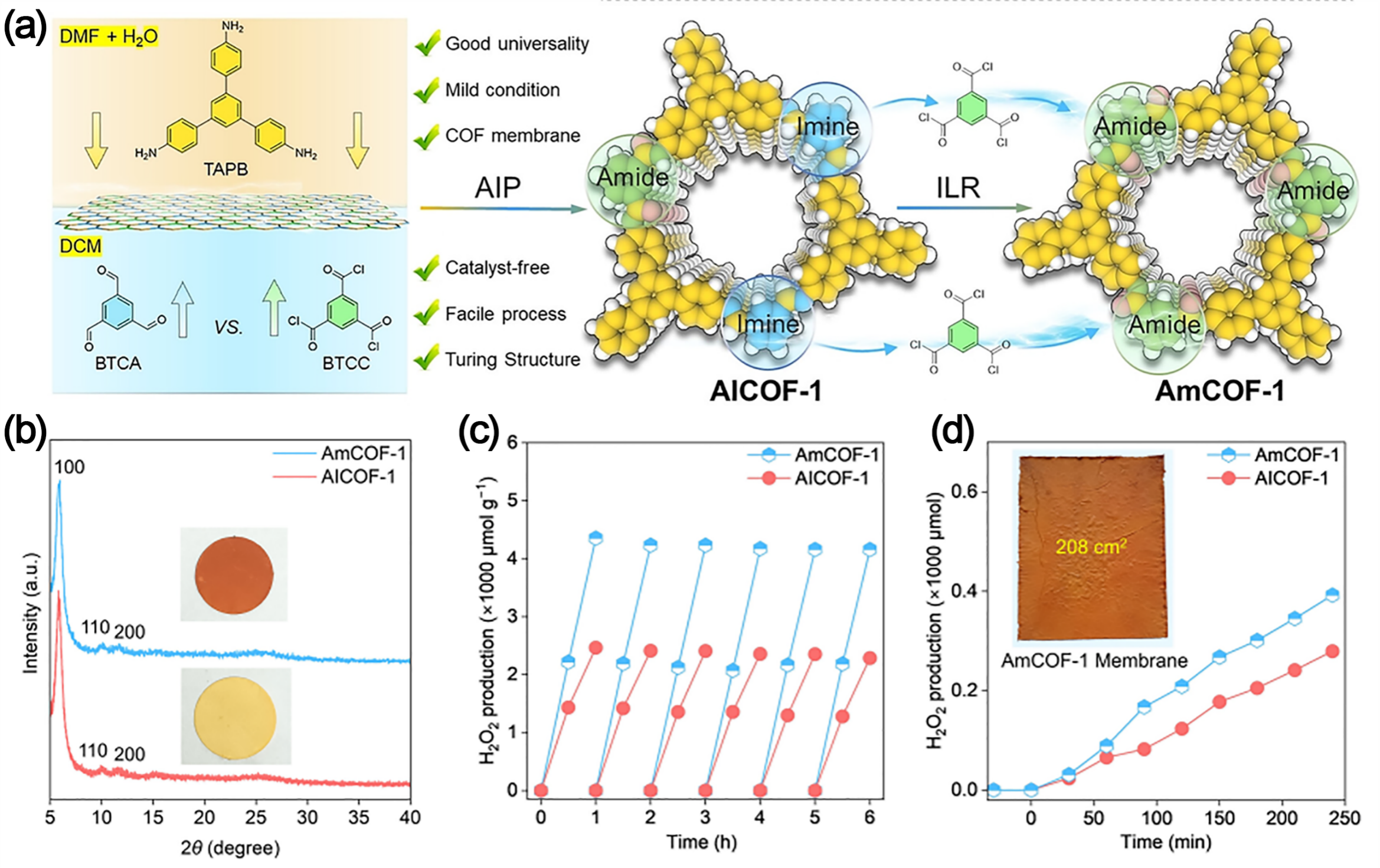
Fig. 25. (a) Synthetic strategy and procedure of the representative AmCOF-1 membrane. (b) XRD patterns. (c) Cyclic H2O2 production over AICOF-1 and AmCOF-1. (d) H2O2 production over AICOF-1 and AmCOF-1 membranes (natural light). Inset: the 208 cm2 AmCOF-1 membrane. Reprinted with permission from Ref. [196]. Copyright 2025, John Wiley and Sons.
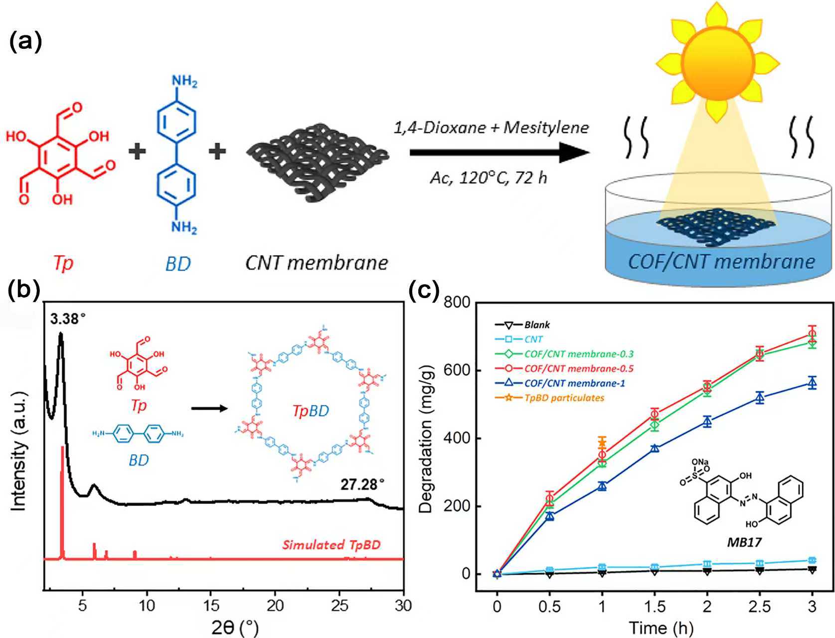
Fig. 26. (a) Diagram of the COF/CNT Membrane Synthesis and the Photocatalytic Degradation Process. (b) PXRD pattern of TpBD. (c) MB17 degradation by various catalysts. Reprinted with permission from Ref. [198]. Copyright 2021, American Chemical Society.
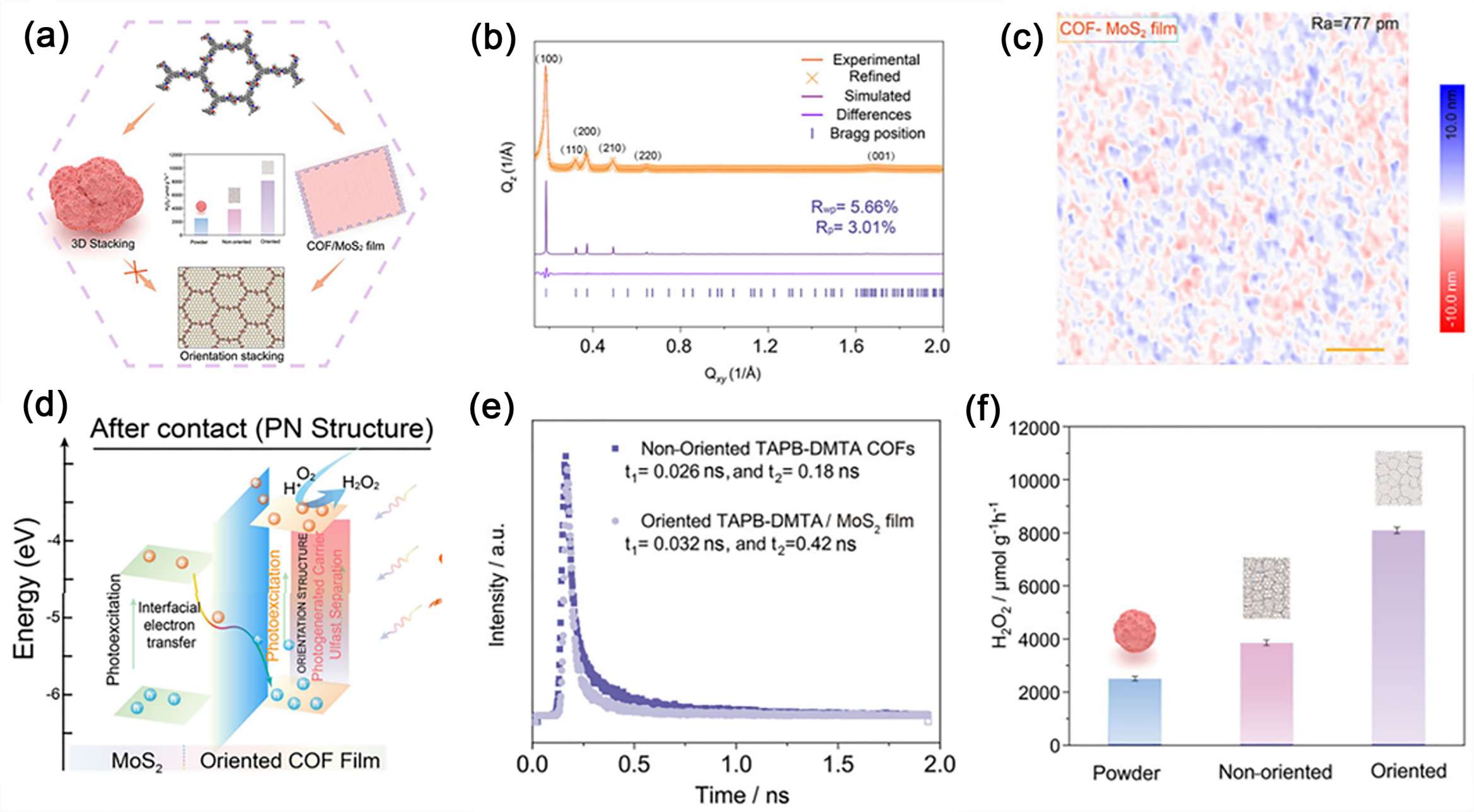
Fig. 27. (a) Schematic illustration of the in-plane oriented COF/MoS2 PN heterostructure membrane. (b) GIXRD pattern and in-plane GIXRD profile of the TAPB-DMTA COF membrane grown on a SiO2/Si substrate. (c) AFM image of a COF membrane grown on a MoS2 substrate. (d) Schematic showing charge separation and photocatalytic H2O2 production in a COF/MoS2 PN heterojunction membrane under visible light. (e) Time-resolved PL decay of oriented TAPB-DMTA/MoS2 membranes and non-oriented TAPT-TFPA COFs. (f) H2O2 production over powder, non-oriented, and oriented TAPB-DMTA COFs. Reprinted with permission from Ref. [203]. Copyright 2025, John Wiley and Sons.
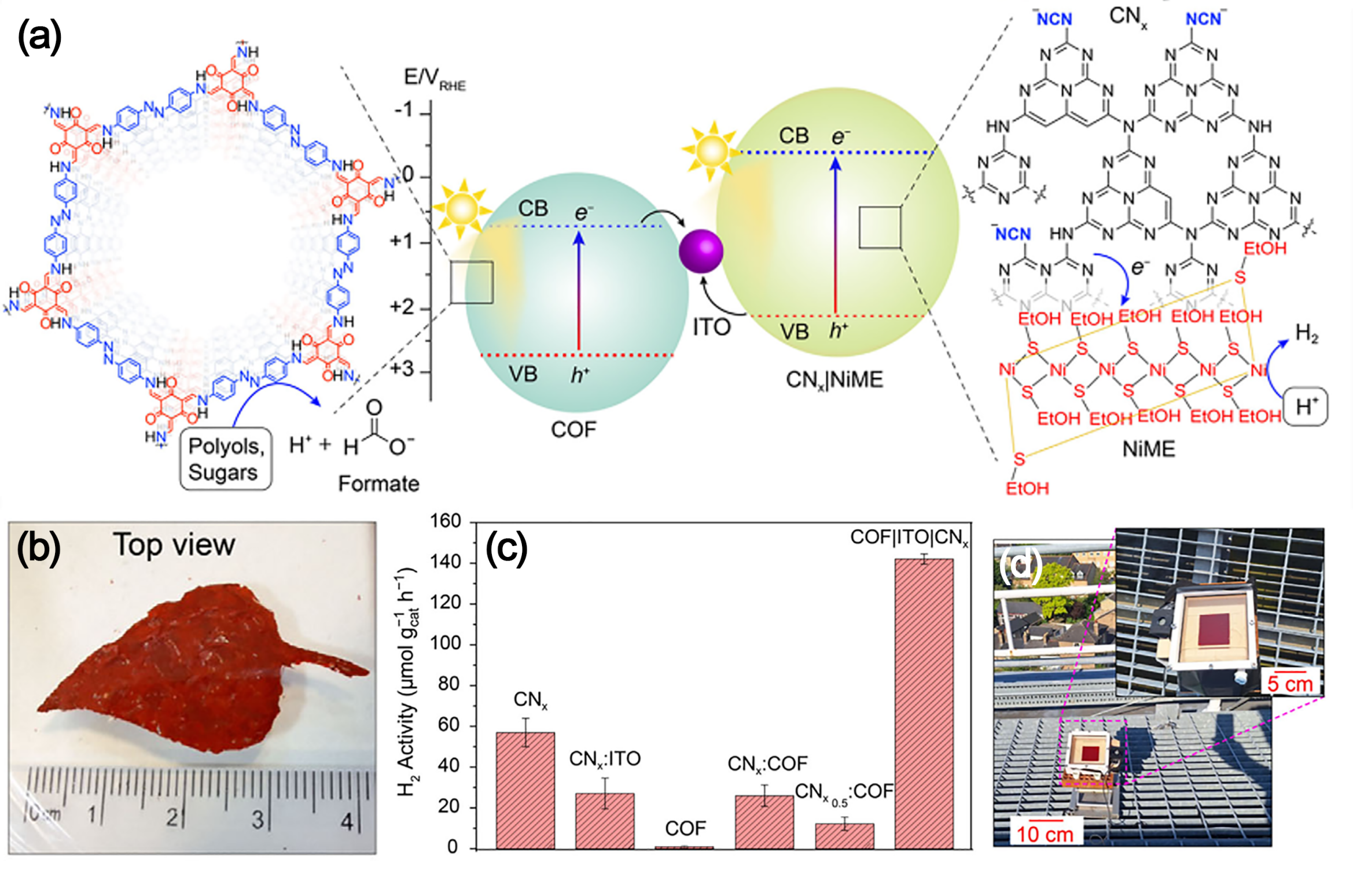
Fig. 28. (a) Energy diagram and schematic of solar reforming over a COF-NiME composite, coupling H2 evolution with oxidation of organics (polyols and sugars) to formate. (b) Photograph of a standalone COF|ITO|CNx. (c) Control experiments for photocatalytic H2 evolution with varied catalyst components and ratios (NiME: 1.25 μmol L-1, H2O, 0.2 mol L-1 EG, 21 h). (d) Photograph of the solar plastic reforming reactor under direct sunlight (inset: close-up view). Reprinted with permission from Ref. [206]. Copyright 2025, John Wiley and Sons.
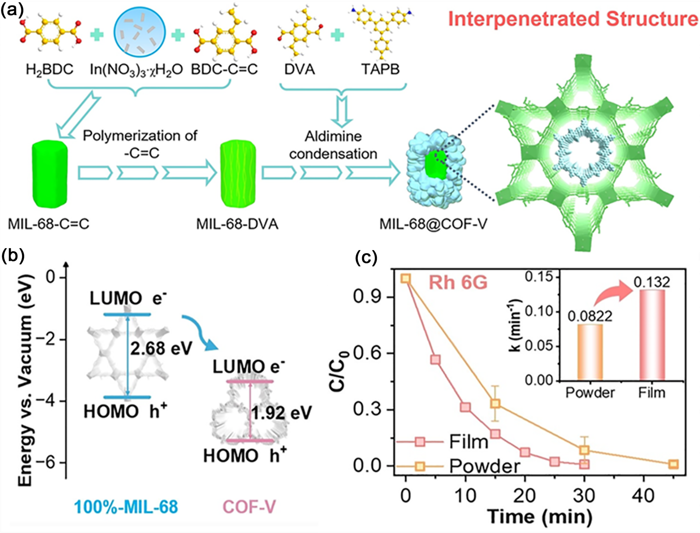
Fig. 29. (a) Schematic illustration of the synthetic process for MIL-68@COF-V heterostructures. (b) Proposed photogenerated electron-transfer pathway within the heterojunction. (c) Comparative degradation of Rh 6G by 10%-MIL-68@COF-V powder and membrane. Reprinted with permission from Ref. [207]. Copyright 2024, John Wiley and Sons.
|
| [1] | Wenmin Lei, Yan Zhang, Dalin Sun, Lin Ban, Heng Zhou, Song Yang, Liquan Jing, Jinguang Hu, Heng Zhang. Transition-metals photocatalysts for lignin valorization toward sustainable biofuel production [J]. Chinese Journal of Catalysis, 2026, 88(9): 35-85. |
| [2] | Bashir Adegbemiga Yusuf, Hennayaka Mudiyanselage Charitha Madusanka Jayawardana, Waleed Yaseen, Jimin Xie, Yilin Deng, Suci Meng, Yongming Li, Abdussamad Mukhtar Mohammed, Aminu Magaji, Min Chen, Meng Xie, Yuanguo Xu. Vacancy-engineered Ru-based CNT electrocatalysts for ampere-level water splitting in alkaline and anion-exchange membrane water electrolyzers [J]. Chinese Journal of Catalysis, 2026, 88(9): 279-294. |
| [3] | Yuhang Sun, Xu Li, Zhongtian Zeng, Hua Wei, Yulong Zhao, Xiaoyan Cai, Liang Mao, Chang-Long Tan, Bo Shen, Yi-Jun Xu. Sulfur-induced charge-site reconstruction and in-situ formed ZnO2 protection enable robust solar H2O2 production [J]. Chinese Journal of Catalysis, 2026, 88(9): 207-217. |
| [4] | Yaowen Wei, Jianwei Wang, Hao Guo, Tao Ban, Yufeng Yue, Di Hu, Haibao Huang. Highly selective oxidation of methane to acetic acid enabled by deficient UiO-66 under mild conditions [J]. Chinese Journal of Catalysis, 2026, 88(9): 356-368. |
| [5] | Shufang Liu, Fengyu Chen, Siyuan Li, Yu-Xin Ye, Gangfeng Ouyang. Recent advances in oxygen-centered organic radicals: Characterization, synthesis, and applications [J]. Chinese Journal of Catalysis, 2026, 88(9): 183-206. |
| [6] | Xiaolong Ma, Zhiqiang Wu, Huiqin Yao, Bin Liu, Zhiliang Jin, Paolo Fornasiero. Charging dynamics engineering: Quantum dots-induced full-space electric field cooperative Ag2S QDs/CoWO₄ S-scheme heterojunction boosting photocatalytic hydrogen evolution [J]. Chinese Journal of Catalysis, 2026, 88(9): 233-246. |
| [7] | Xiangfeng Chen, Siyu Huang, Yuhang Yang, Jiahao Ni, Cheng Fang, Yang-Fan Xu, Dai-Bin Kuang. Hybrid photocatalysis with halide perovskite materials [J]. Chinese Journal of Catalysis, 2026, 88(9): 9-34. |
| [8] | Fengjuan Guo, Chunyao Ma, Yue Huang, Sitong Hang, Junwei Ma, Hongtao Gao. Unveiling the dominant distal-alternating hybrid mechanism in B-modulated Mo2TiC2Tx/MoO2 MXene for highly selective ambient NRR [J]. Chinese Journal of Catalysis, 2026, 87(8): 269-281. |
| [9] | Gaoxiong Liu, Rundong Chen, Bingquan Xia, Xianlong Zhou, Laiquan Li, Shantang Liu. Thiadiazole-functionalized covalent triazine frameworks for constructing S-scheme heterojunctions enabling boosted H2O2 photosynthesis [J]. Chinese Journal of Catalysis, 2026, 87(8): 170-184. |
| [10] | Hao Wu, Xinyu Zeng, Wang Wang, Bei Cheng, Jingzhao Cheng, Jingsan Xu, Shaowen Cao. The organic-inorganic S-scheme heterojunction with enhanced charge separation simultaneously catalyze the production of hydrogen and imine [J]. Chinese Journal of Catalysis, 2026, 87(8): 185-196. |
| [11] | Keke Zhang, Fulin Zhang, Yuexin Wang, Fengwei Huang, Kanghui Xiong, Xiang-Kui Gu, Xianjun Lang. Tweaking the electron push-pull effect of vinylene-linked thienothiophene covalent organic frameworks for enhanced selective photocatalysis [J]. Chinese Journal of Catalysis, 2026, 87(8): 206-216. |
| [12] | Shijie Li, Rui Li, Yanping Liu, Xin Yu, Deyun Ma, Jianhui Jiang, Xiaosong Zhou, Chunqiang Zhuang, Zaiwang Zhao, Wei Jiang. Augmented reactive oxygen species generation in Ag/AgBr/C3N5 via LSPR-enhanced S-scheme charge transfer for efficient photocatalytic antibiotic wastewater remediation [J]. Chinese Journal of Catalysis, 2026, 87(8): 126-139. |
| [13] | Ke Li, Yi Luo, Chenning Cai, Zemin Zheng, Gang Yu, Jianqiang Hu, Shengli Chen. WN enhanced metal-N-C platform for ultra-stable Pt oxygen reduction electrocatalyst in fuel cell [J]. Chinese Journal of Catalysis, 2026, 87(8): 230-242. |
| [14] | Bowen Li, Changlin Lin, Qi Wang, Yongfeng Lun, Jun Fang, Shuqin Song, Yi Wang. Ligand-shell engineering of a Au25 nanocluster boosting CO2 electroreduction to syngas with tunable range proportion [J]. Chinese Journal of Catalysis, 2026, 87(8): 396-409. |
| [15] | Shaokang Yu, Meng Dong, Ming Xu, Yijia Lv, Zhiyang Peng, Weitao Zhang, Dabing Guo, Yixie Wang, Zhen Xue, Yusen Yang, Hao Li, Mingfei Shao. Boosting co-thermal coupled in-situ reduction of morphology- engineered carbonate via preparing distinct crystalline phases [J]. Chinese Journal of Catalysis, 2026, 86(7): 149-159. |
| Viewed | ||||||
|
Full text |
|
|||||
|
Abstract |
|
|||||


