
Chinese Journal of Catalysis ›› 2026, Vol. 91: 1-49.DOI: 10.1016/S1872-2067(26)65230-8
• Reviews • Next Articles
Yang Wana, Bao Zoua, Xianghai Songa, Yan Liua,*( ), Jianmin Luob, Xin Liua, Xin Lic,*(), Pengwei Huoa,*()
Received:2026-04-25
Accepted:2026-06-22
Online:2026-12-18
Published:2026-10-13
About author:Yan Liu received her B.A. degree from Nanjing Normal University in 2003, and Ph.D degree from Jiangsu University in 2011. From 2018-2019, she worked as a visiting scholar at the University of California, Irvine (USA). Her research interests currently focus on design of functional materials and their applications in engineering and catalysis. She has published more than 60 peer-reviewed papers.Yang Wan: Writing - review & editing, Writing - original draft, Data curation, Conceptualization; Bao Zou, Xianghai Song, and Xin Liu: Data curation, Software, Formal analysis; Jianmin Luo: Project administration, Validation, Supervision; Yan Liu, and Xin Li: Project administration, Methodology, Review & editing; Pengwei Huo: Project administration, Methodology, Investigation, Funding acquisition.
Supported by:Yang Wan, Bao Zou, Xianghai Song, Yan Liu, Jianmin Luo, Xin Liu, Xin Li, Pengwei Huo. Recent advances in catalytic conversion technologies for plastic waste upgrading[J]. Chinese Journal of Catalysis, 2026, 91: 1-49.
Add to citation manager EndNote|Ris|BibTeX
URL: https://www.cjcatal.com/EN/10.1016/S1872-2067(26)65230-8
| Type of treatment | Advantages | Disadvantages | Applicable scenarios |
|---|---|---|---|
| Incineration | significantly reduces landfill space; recovers thermal energy | produces toxic gases; high carbon emissions; generates ash residue | mixed non-recyclable plastics with high calorific value |
| Landfill | simple operation; low cost | occupies large land area; pollutes groundwater and soil | contaminated plastics that cannot be recycled |
| Mechanical recycling | Simple process and low cost; direct reuse of plastics | decreased mechanical properties; high requirement for raw material purity | clean, single-polymer plastics (e.g., PET bottles, HDPE containers) |
| Photocatalysis | ambient temperature and pressure; green, low energy consumption | long reaction time; low reaction stability; plastics need to be pretreated | thin plastic films or small molecules after pretreatment |
| Thermal catalysis | high conversion rate and stability; technological maturity; handle complex plastics | prone to coking and deactivation; release toxic gases; Relies on noble metals/hydrogen | large-scale continuous processing of mixed plastics; high-value products |
| Electrocatalysis | controllable reaction pathways; can use green electricity | electrodes prone to corrosion; plastics must be pretreated | directed synthesis of high-value chemicals (e.g., small-molecule acids, esters) |
| Photothermalcatalysis | high energy utilization efficiency; mild conditions | requires high-intensity light source; poor catalyst stability; difficult product purity control | selective conversion of recalcitrant plastics (e.g., PVC) |
| Photoelectrocatalysis | synergy of light and electricity; high efficiency; can produce H2 | complex system design (requires semiconductor electrodes); difficult to scale up | small-scale production of specialty chemicals |
| Biocatalysis | mild conditions; high selectivity; strong substrate specificity | enzymes easily inactivated; long cycle time; narrow application range | degradable plastics; mixed plastics; conversion under extreme environments (e.g., marine, soil) |
Table 1 Existing plastic treatment technologies.
| Type of treatment | Advantages | Disadvantages | Applicable scenarios |
|---|---|---|---|
| Incineration | significantly reduces landfill space; recovers thermal energy | produces toxic gases; high carbon emissions; generates ash residue | mixed non-recyclable plastics with high calorific value |
| Landfill | simple operation; low cost | occupies large land area; pollutes groundwater and soil | contaminated plastics that cannot be recycled |
| Mechanical recycling | Simple process and low cost; direct reuse of plastics | decreased mechanical properties; high requirement for raw material purity | clean, single-polymer plastics (e.g., PET bottles, HDPE containers) |
| Photocatalysis | ambient temperature and pressure; green, low energy consumption | long reaction time; low reaction stability; plastics need to be pretreated | thin plastic films or small molecules after pretreatment |
| Thermal catalysis | high conversion rate and stability; technological maturity; handle complex plastics | prone to coking and deactivation; release toxic gases; Relies on noble metals/hydrogen | large-scale continuous processing of mixed plastics; high-value products |
| Electrocatalysis | controllable reaction pathways; can use green electricity | electrodes prone to corrosion; plastics must be pretreated | directed synthesis of high-value chemicals (e.g., small-molecule acids, esters) |
| Photothermalcatalysis | high energy utilization efficiency; mild conditions | requires high-intensity light source; poor catalyst stability; difficult product purity control | selective conversion of recalcitrant plastics (e.g., PVC) |
| Photoelectrocatalysis | synergy of light and electricity; high efficiency; can produce H2 | complex system design (requires semiconductor electrodes); difficult to scale up | small-scale production of specialty chemicals |
| Biocatalysis | mild conditions; high selectivity; strong substrate specificity | enzymes easily inactivated; long cycle time; narrow application range | degradable plastics; mixed plastics; conversion under extreme environments (e.g., marine, soil) |
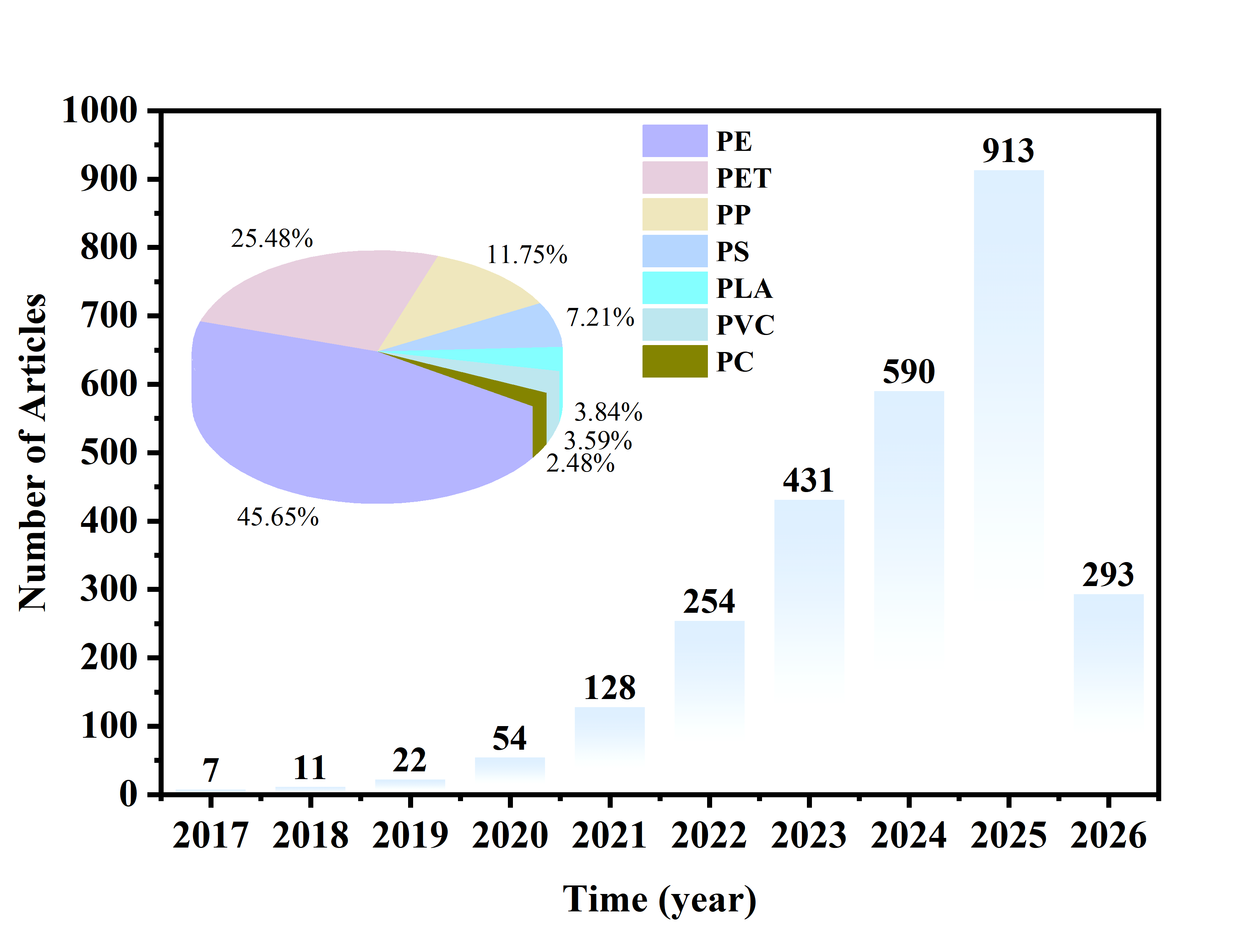
Fig. 1. Proportion of various plastics in upcycling conversion and the number of articles on plastic upcycling published between 2017 and 2026, based on a Web of Science search using the keywords: “upcycling” and “plastic” (conducted on April 30, 2026).
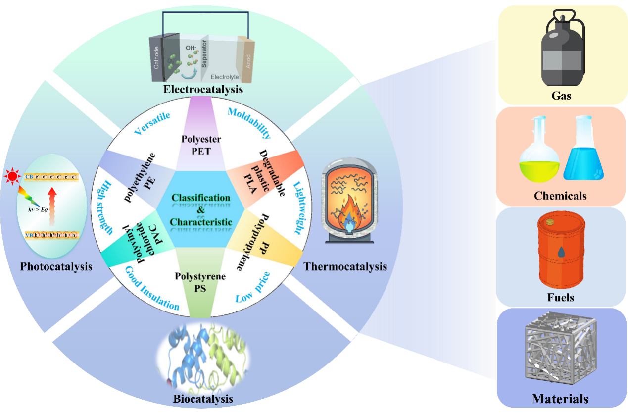
Fig. 2. Plastic classification, advantages, catalytic upcycling ways, and value-added products.

Fig. 3. Schematic diagram of direct and indirect pathways for plastic upcycling.
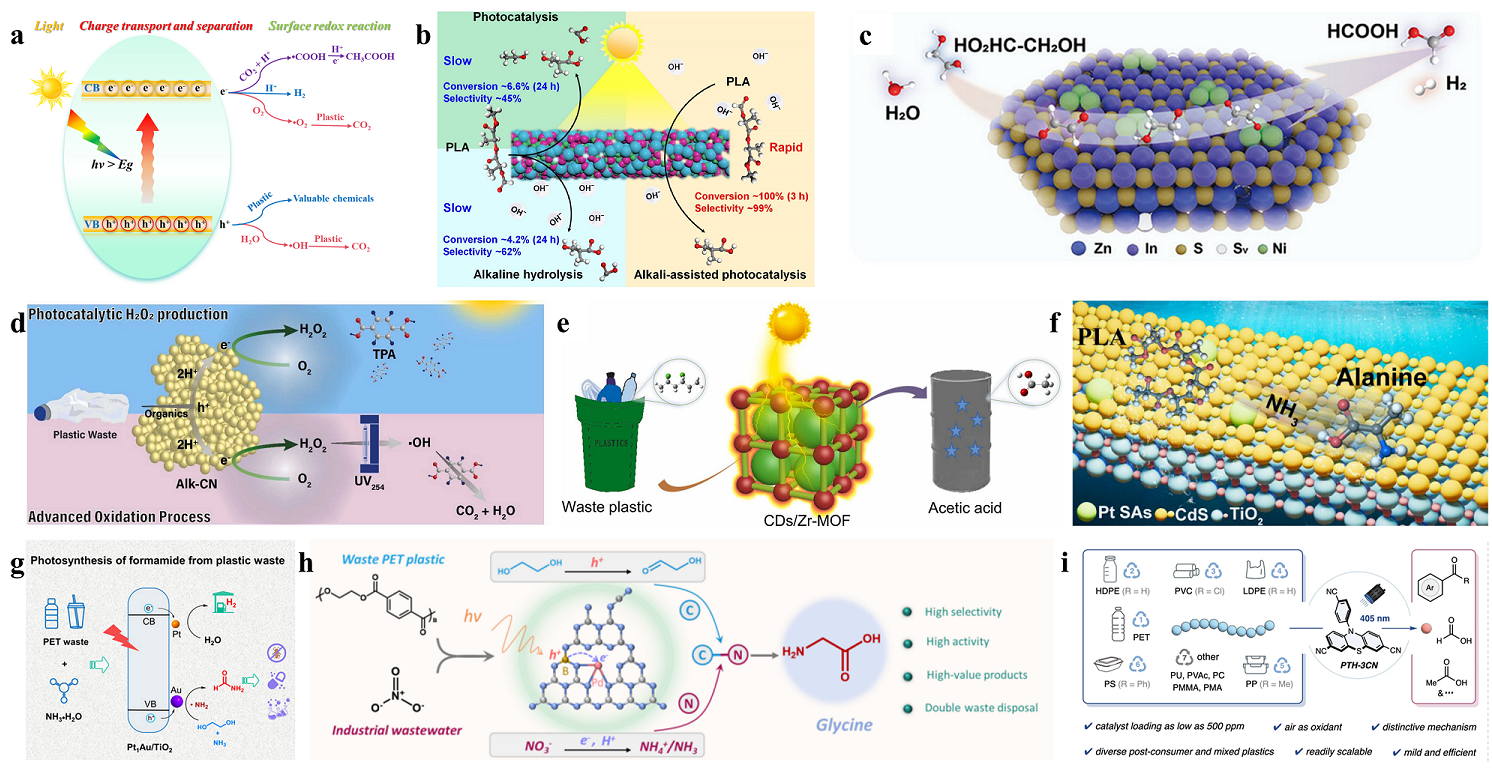
Fig. 4. (a) Schematic diagram of the photocatalytic conversion mechanism in plastics. (b) Photocatalytic conversion of PLA plastics over ZnInFe-MMMO. Reprinted with permission from Ref. [42]. Copyright 2024, John Wiley and Sons. (c) Photocatalytic conversion of PLA plastics on CdS-H@1NiS-0.5PdS. Reprinted with permission from Ref. [43]. Copyright 2025, Elsevier. (d) Schematic diagram of the complete mineralization of PET waste by g-C3N4 catalyst under photocatalytic conditions. Reprinted with permission from Ref. [44]. Copyright 2025, Elsevier. (e) Schematic diagram of photocatalytic conversion of PVC plastic on CDs/Zr-MOF. Reprinted with permission from Ref. [45]. Copyright 2023, Elsevier. (f) Schematic diagram of Pt single-atom photocatalyst converting PLA into alanine. Reprinted with permission from Ref. [46]. Copyright 2025, American Chemical Society. (g) Schematic diagram of the Pt1Au/TiO2 photocatalyst converting PET to FA. Reprinted with permission from Ref. [47]. Copyright 2025, John Wiley and Sons. (h) Schematic diagram of the Pd-B dual-atom photocatalyst converting PET and NO3- into glycine. Reprinted with permission from Ref. [48]. Copyright 2026, Springer Nature. (i) Schematic diagram of the organic catalyst PTH-3CN of benzothiazine derivatives performing photocatalytic upgrading of plastics. Reprinted with permission from Ref. [49]. Copyright 2026, Springer Nature.
| Catalyst | Plastic | Conditions | Products | Ref. |
|---|---|---|---|---|
| TiO2 | PP | pH=3, 50 h, and sunlight irradiation | CO2 | [ |
| CdS QDs | PET | 8 h, Xe lamp irradiation | formate, acetate, and H2 | [ |
| CoS/CeO2 | PET | 6 h, Xe lamp irradiation | CO2, CO, CH4 | [ |
| ZnInFe-MMO | PLA | 0.5 mol L-1 NaOH solution, 3 h, and Xe lamp irradiation | sodium lactate | [ |
| S-BiVO4/In2S3 | PLA | 5 h, Xe lamp (λ ≥ 420 nm) irradiation | acetic acid | [ |
| d-NiPS3/CdS | PLA and PET | 9 h, full-spectrum irradiation | H2, organic acid | [ |
| Alk-CN | PLA and PET | 7 d, UV254 irradiation | TPA, H2O2 | [ |
| CDs/Zr-MOF | PVC | 60 h, light illumination | acetic acid | [ |
| Pt SAs-CTA | PLA | NH3·H2O, Xe lamp (λ > 420 nm) | alanine | [ |
| Diatomic Pd-B | PET | 24 h, Xe lamp (320 nm < λ < 780 nm) | glycine | [ |
| PTH-3CN | PS, PE, PP, and PVC | 405 nm LED illumination | benzoic acid, formic acid, and acetic acid | [ |
Table 2 Photocatalytic conversion of plastics over different catalysts.
| Catalyst | Plastic | Conditions | Products | Ref. |
|---|---|---|---|---|
| TiO2 | PP | pH=3, 50 h, and sunlight irradiation | CO2 | [ |
| CdS QDs | PET | 8 h, Xe lamp irradiation | formate, acetate, and H2 | [ |
| CoS/CeO2 | PET | 6 h, Xe lamp irradiation | CO2, CO, CH4 | [ |
| ZnInFe-MMO | PLA | 0.5 mol L-1 NaOH solution, 3 h, and Xe lamp irradiation | sodium lactate | [ |
| S-BiVO4/In2S3 | PLA | 5 h, Xe lamp (λ ≥ 420 nm) irradiation | acetic acid | [ |
| d-NiPS3/CdS | PLA and PET | 9 h, full-spectrum irradiation | H2, organic acid | [ |
| Alk-CN | PLA and PET | 7 d, UV254 irradiation | TPA, H2O2 | [ |
| CDs/Zr-MOF | PVC | 60 h, light illumination | acetic acid | [ |
| Pt SAs-CTA | PLA | NH3·H2O, Xe lamp (λ > 420 nm) | alanine | [ |
| Diatomic Pd-B | PET | 24 h, Xe lamp (320 nm < λ < 780 nm) | glycine | [ |
| PTH-3CN | PS, PE, PP, and PVC | 405 nm LED illumination | benzoic acid, formic acid, and acetic acid | [ |
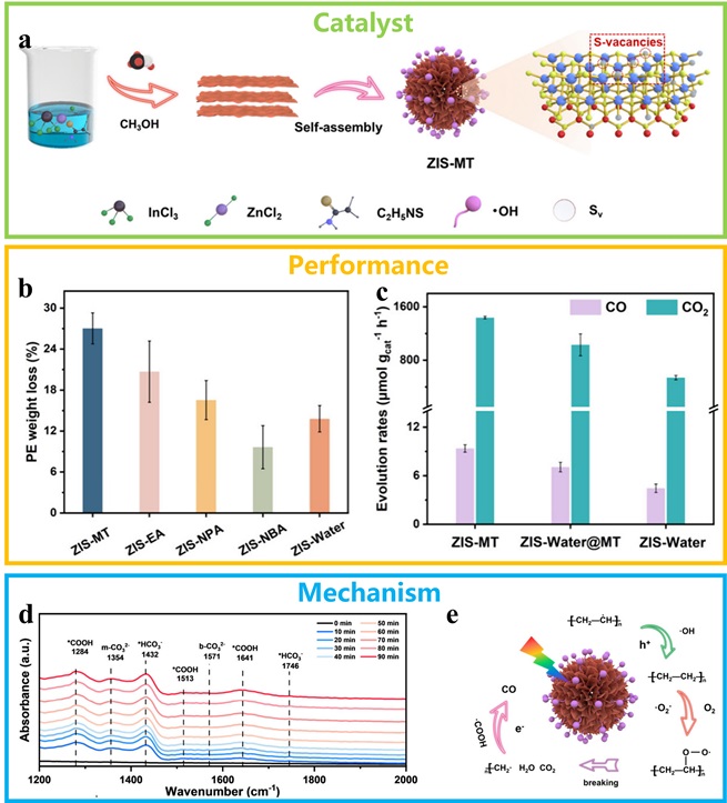
Fig. 5. (a) Schematic diagram of the preparation process for the ZIS-MT catalyst. (b) The effect of different catalysts on the weight loss of PE plastic. (c) Graph of gas yield from degradation. (d) In-situ infrared images of the degradation process. (e) Diagram of the degradation mechanism. Reprinted with permission from Ref. [97]. Copyright 2025, American Chemical Society.
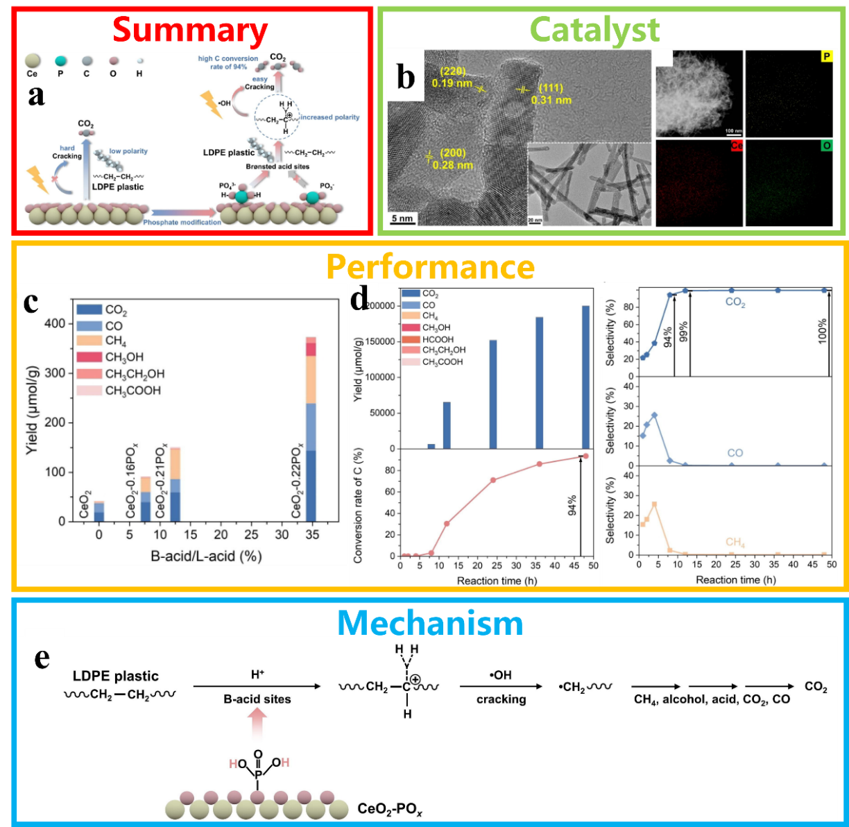
Fig. 6. (a) Schematic diagram illustrating the conversion of PE plastic into C1. (b) TEM, HRTEM and EDS elemental mapping images of CeO2-nPOχ. (c) The yield of LDPE photodegradation for different CeO2-based photocatalysts, and the effect of the B-acid to L-acid ratio on the yield. (d) Diagram showing the variation in product selectivity for CO2, CO and CH4 over time. (e) Reaction pathways for the photocatalytic conversion of PE plastic into C1 products. Reprinted with permission from Ref. [98]. Copyright 2024, Elsevier.
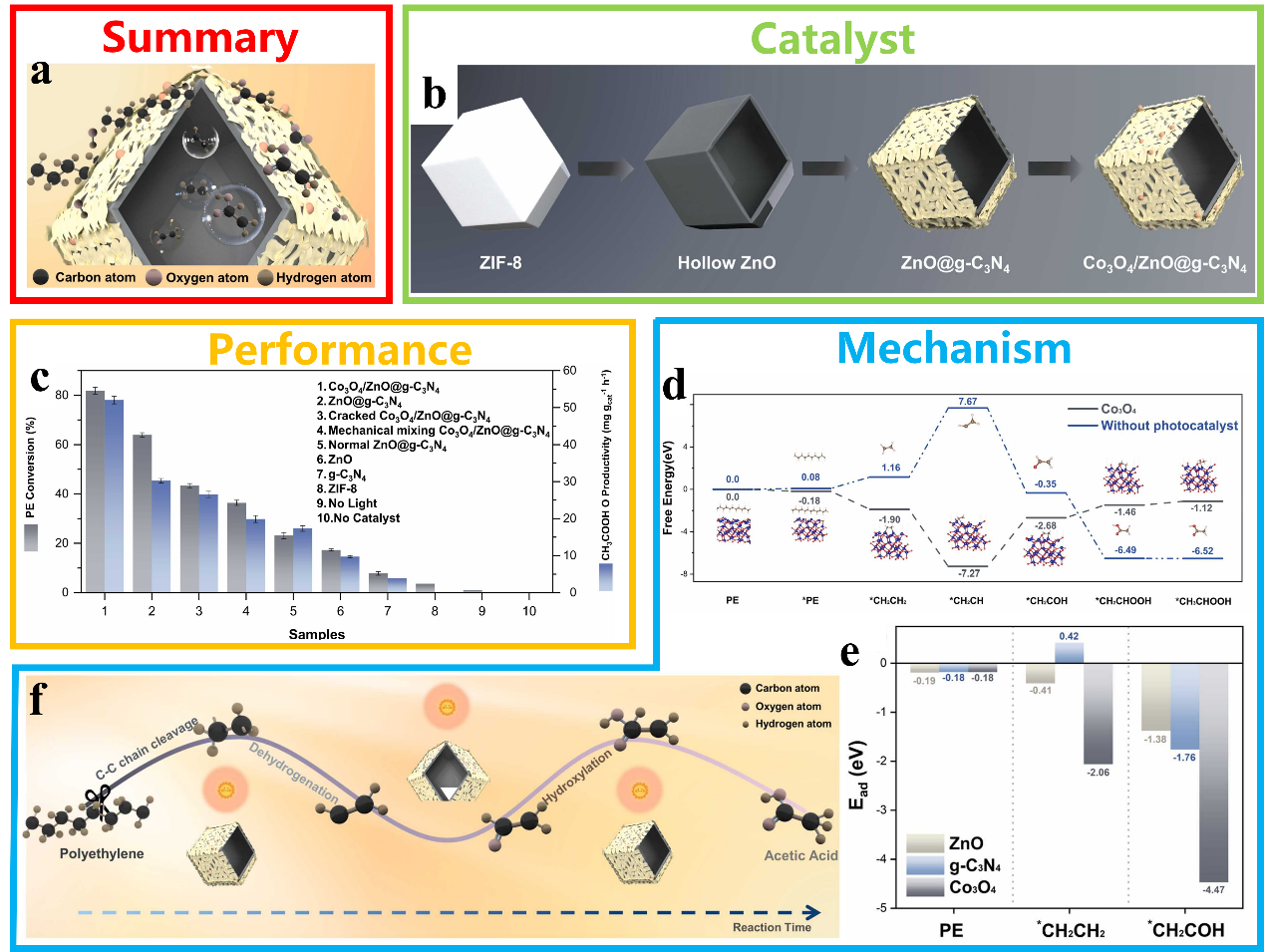
Fig. 7. (a) Schematic illustration of the series-parallel structured catalyst (Co3O4/ZnO@g-C3N4) for the cleavage of C-C bonds in plastics. (b) The synthesis of Co3O4/ZnO@g-C3N4 material. (c) The ability of the as-synthesized photocatalysts to upgrade PE to AcOH under photocatalytic conditions; d: Calculated free energy changes for each step in the photocatalytic upgrading of PE catalyzed by Co3O4/ZnO@g-C3N4. (e) The binding energies of PE and key reaction intermediates at the ZnO, g-C3N4, and Co3O4 sites on the Co3O4/ZnO@g-C3N4 surface. (f) Mechanism of the PE photocatalytic valorization into AcOH over Co3O4/ZnO@g-C3N4. Reprinted with permission from Ref. [102]. Copyright 2025, Elsevier.
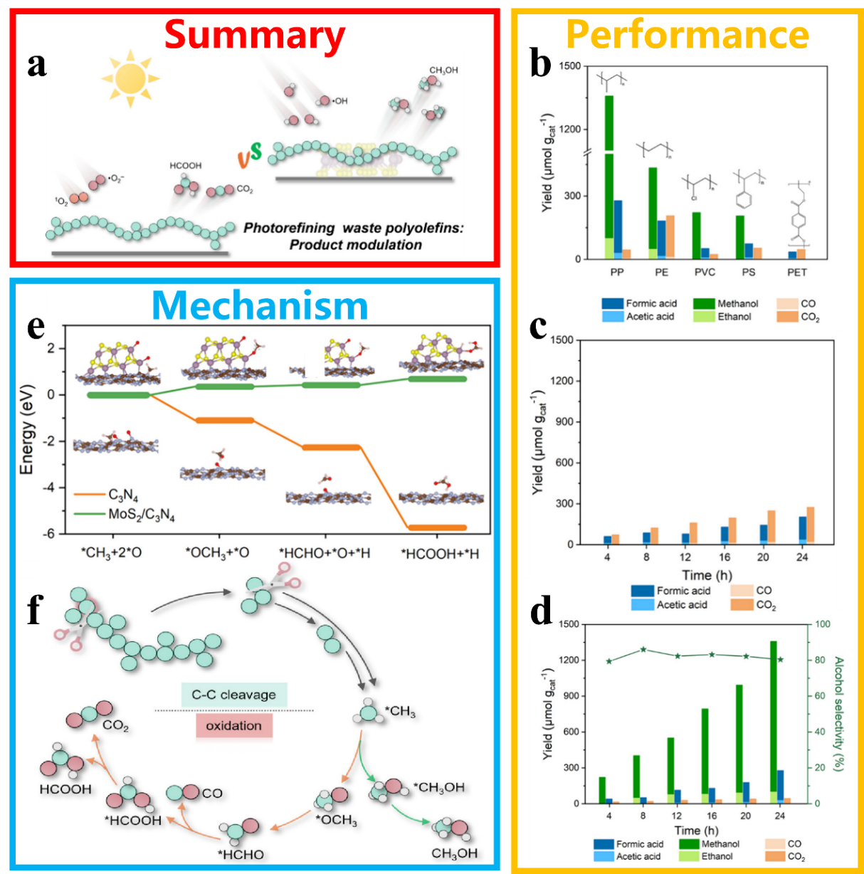
Fig. 8. (a) Scheme for product control in the photocatalytic conversion of waste polyolefins. (b) Photocatalytic conversion performance of different plastics on MoS2/C3N4. The change in product over time on C3N4 (c) and MoS2/C3N4 (d). (e) The calculated reaction pathways and free energy diagrams for the generation of HCOOH on different catalysts. (f) Possible mechanisms for the transformation of plastics into different products. Reprinted with permission from Ref. [103]. Copyright 2025, American Chemical Society.
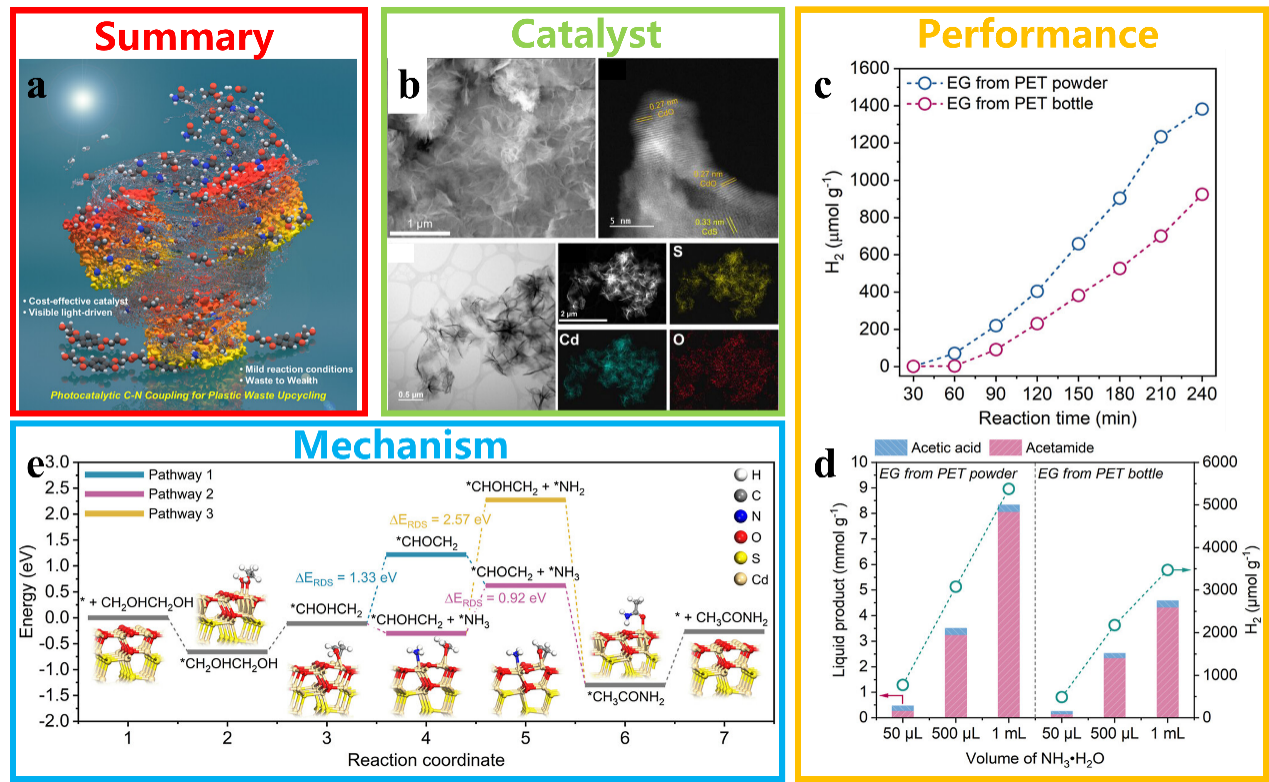
Fig. 9. (a) Scheme for the upgraded utilisation of plastic waste using photocatalytic C-N coupling technology. (b) Morphology of CdS catalysts as observed by SEM, TEM and HRTEM, and EDS elemental mapping. (c) The yield of H2 in the photocatalytic coupling reaction of PET-derived EG with an ammonia solution. (d) The effect of varying volumes of NH3·H2O on the liquid products and H2 yield in a photocatalytic C-N coupling system. Reprinted with permission from Ref. [104]. Copyright 2025, American Chemical Society. (e) Free-energy diagram of the key reaction pathways and corresponding intermediates for the C-N coupling reaction on CdS.

Fig. 10. (a) The process and products of thermocatalytic conversion of plastics. Reprinted with permission from Ref. [134]. Copyright 2020, AAAS. (b) Conversion of HDPE using ZSM-5 zeolites with different Si/Al ratios. Reprinted with permission from Ref. [135]. Copyright 2025, American Chemical Society. (c) Schematic diagram of the conversion of PE plastic using M720 zeolite catalyst. Reprinted with permission from Ref. [136]. Copyright 2024, Royal Society of Chemistry. (d) Schematic diagram of the use of FeCoAl-LDO catalysts for the thermocatalytic conversion of PS to a product rich in monocyclic aromatics. Reprinted with permission from Ref. [137]. Copyright 2025, Elsevier. (e) Schematic diagram of PE recycling over Pt/SrTiO3. Reprinted with permission from Ref. [138]. Copyright 2019, American Chemical Society. (f) Schematic diagram of the conversion of PE plastic into aromatic compounds on a Pt/Al2O3 catalyst. Reprinted with permission from Ref. [139]. Copyright 2020, AAAS.
| Catalyst | Plastic | Conditions | Products | Ref. |
|---|---|---|---|---|
| ZSM-5 | HDPE | 450 °C | gas and oil | [ |
| FeCoAl-LDO | PS | 500 °C | C7-C12 light aromatics | [ |
| SrTiO3 | PE | 300 °C, 170 psi H2 | liquid products | [ |
| Pt/γ-Al2O3 | PE | 280 °C | long-chain alkyl aromatics | [ |
| Ru/Nb2O5 | PET, PS, PC | 200-320 °C, H2 | aromatic monomers | [ |
| MCM-41 and HZSM-5 | mixed packaging plastics | 500 and 550 °C | BTEX | [ |
| UiO-66 | PE | 400 °C | liquid and gaseous hydrocarbons | [ |
| Single-atom Ni/WO2.72 | PE | 240-260 °C and 3 MPa H2 | C5-20 liquid fuels | [ |
| RuLa-DA | PC | 550 °C (hydropyrolysis) and 200 °C, 0.25 MPa H2 (hydrogenation) | cyclohexanol | [ |
Table 3 Thermocatalytic conversion of plastics over different catalysts.
| Catalyst | Plastic | Conditions | Products | Ref. |
|---|---|---|---|---|
| ZSM-5 | HDPE | 450 °C | gas and oil | [ |
| FeCoAl-LDO | PS | 500 °C | C7-C12 light aromatics | [ |
| SrTiO3 | PE | 300 °C, 170 psi H2 | liquid products | [ |
| Pt/γ-Al2O3 | PE | 280 °C | long-chain alkyl aromatics | [ |
| Ru/Nb2O5 | PET, PS, PC | 200-320 °C, H2 | aromatic monomers | [ |
| MCM-41 and HZSM-5 | mixed packaging plastics | 500 and 550 °C | BTEX | [ |
| UiO-66 | PE | 400 °C | liquid and gaseous hydrocarbons | [ |
| Single-atom Ni/WO2.72 | PE | 240-260 °C and 3 MPa H2 | C5-20 liquid fuels | [ |
| RuLa-DA | PC | 550 °C (hydropyrolysis) and 200 °C, 0.25 MPa H2 (hydrogenation) | cyclohexanol | [ |

Fig. 11. (a) Schematic illustration of the selective cleavage of C-O/C-C bonds in plastics by Ru-based catalysts to form aromatic compounds. Reprinted with permission from Ref. [151]. Copyright 2020, John Wiley and Sons. (b) Schematic diagram of the conversion of mixed plastics into BETX using a tandem catalyst. Reprinted with permission from Ref. [152]. Copyright 2023, Elsevier. (c) Schematic diagram of plastic conversion into useful hydrocarbons using the UiO-66 catalyst. Reprinted with permission from Ref. [153]. Copyright 2024, John Wiley and Sons. (d) Schematic diagram of plastic to fuel conversion over WOX-supported single-atom Ni catalyst. Reprinted with permission from Ref. [154]. Copyright 2025, American Chemical Society. (e) Schematic diagram of plastic to EG and p-xylene (PX) conversion over Cu/UiO-66-NH2-A catalyst. Reprinted with permission from Ref. [155]. Copyright 2025, John Wiley and Sons. (f) Schematic diagram of conversion of PC plastic to cyclohexanol over RuLa dual-atom catalyst. Reprinted with permission from Ref. [156]. Copyright 2025, John Wiley and Sons.
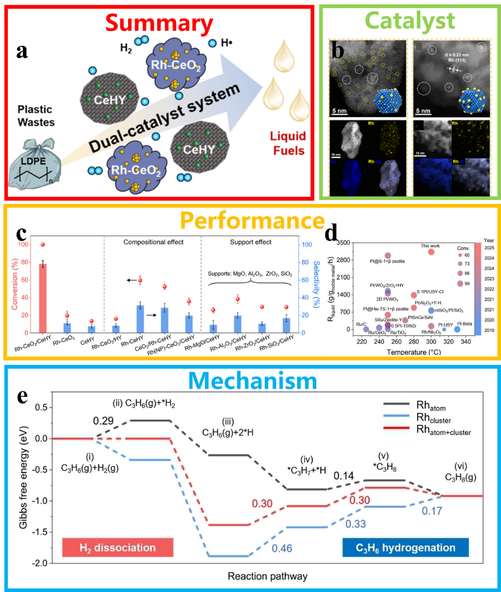
Fig. 12. (a) Schematic diagram of the hydrocracking of LDPE into liquid fuels using a CeHY+Rh-CeO2 catalyst. (b) HAADF-STEM and EDX mapping images of Rh-CeO2 and Rh-Al2O3. (c) Performance of different catalysts in the conversion of LDPE plastic. (d) Comparison of this work with other works. (e) Gibbs free energy profiles of the reaction pathways on different catalyst models. Reprinted with permission from Ref. [166]. Copyright 2025, American Chemical Society.
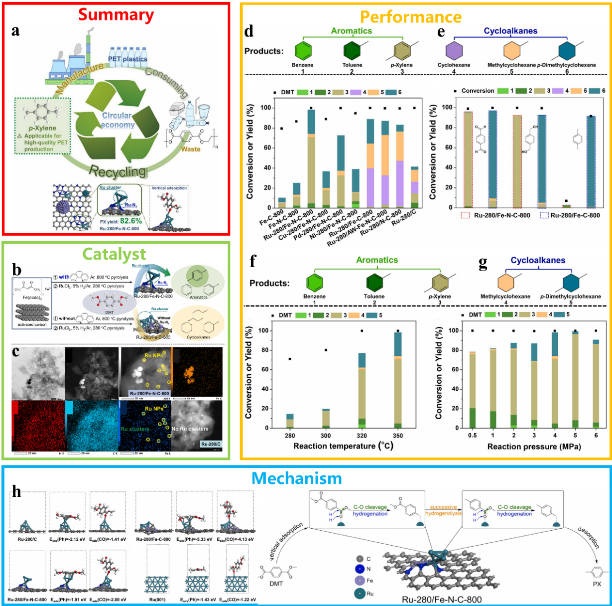
Fig. 13. (a) Schematic diagram of the HDO reaction using a RuFe bimetallic catalyst for the selective cleavage of C-C/C-O bonds to convert PET. (b) Schematic diagram of the synthesis of a RuFe bimetallic catalyst. (c) TEM, HRTEM and elemental mapping of the RuFe bimetallic catalyst. Factors affecting performance: catalyst (d,e), temperature (f), and pressure (g). (h) The adsorption configurations of DMT on different catalysts, their corresponding energies, and the possible reaction pathway for the HDO reaction. Reprinted with permission from Ref. [170]. Copyright 2024, Elsevier.
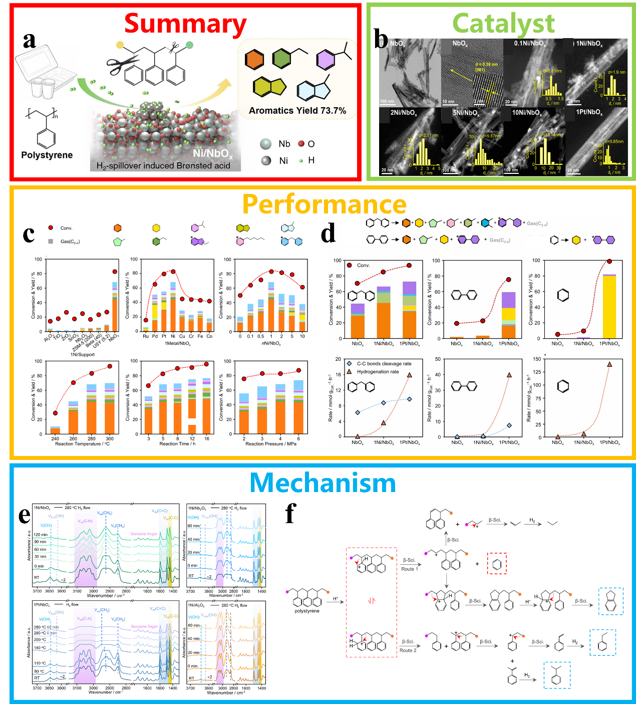
Fig. 14. (a) Schematic diagram of the conversion of PS plastic using a Ni/NbOx catalyst in a solvent-free system. (b) Morphology and particle size distribution of Ni/NbOx catalysts. (c) Comparison of the catalytic performance of Ni/NbOx with various reference catalysts in the hydrocracking of PS plastics. (d) Diagram of hydrogenation rates and C-C bond cleavage rates for different molecular models on different catalysts. (e) In-situ IR spectra of hydrocracked PS on various catalysts. (f) Possible pathway diagram for the hydrocracking of PS over 1Ni/NbOx catalyst. Reprinted with permission from Ref. [171]. Copyright 2026, Elsevier.
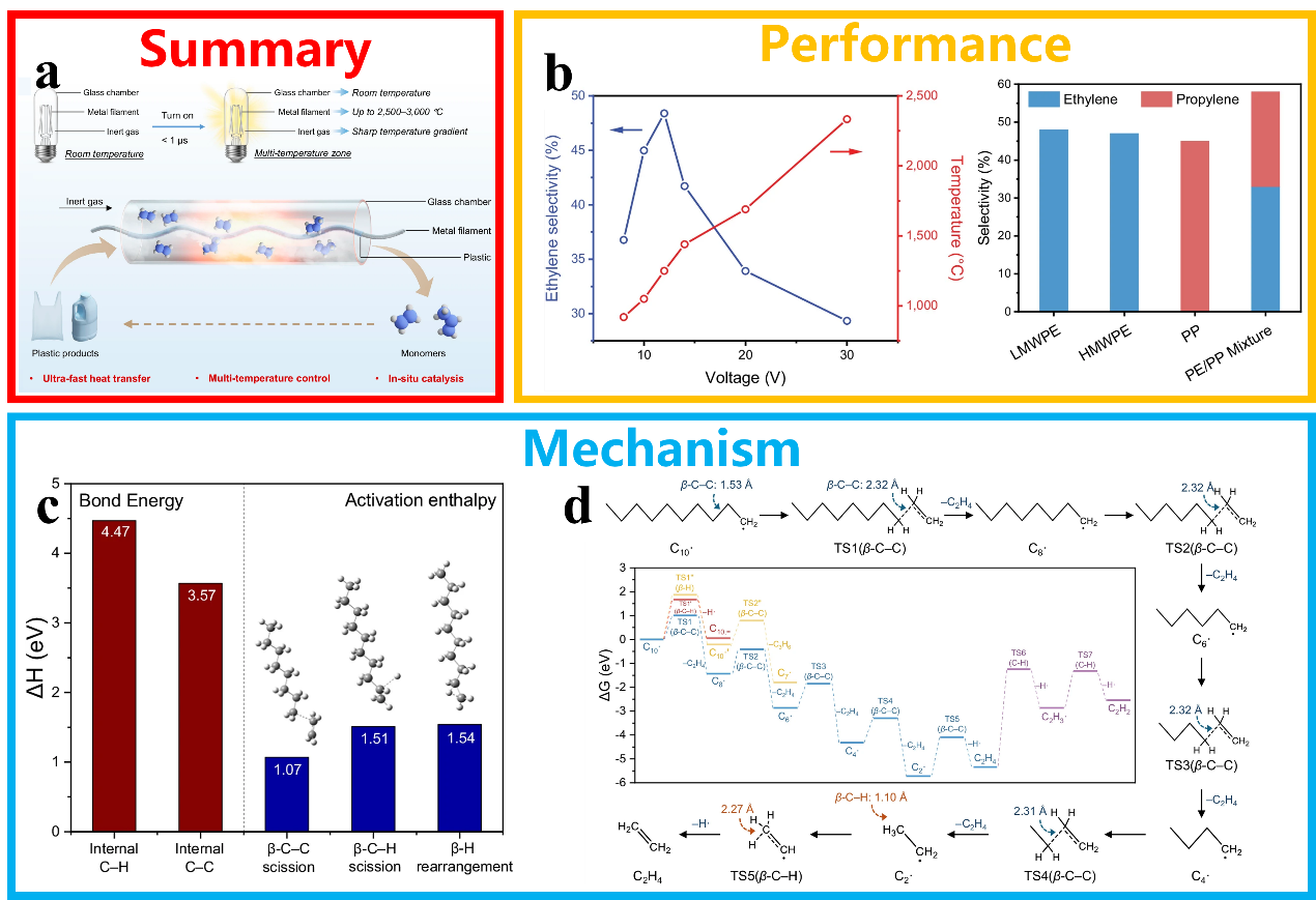
Fig. 15. (a) Schematic diagram of the depolymerisation of polyolefin plastics into monomers using high-temperature catalytic metal wires. (b) Performance diagram for depolymerised polyolefin plastics. (c) Bond breaking energies for β-C-C and β-C-H bonds obtained from DFT calculations. (d) The reaction free energy of the decomposition of the transition-state intermediate and the possible reaction pathways. Reprinted with permission from Ref. [172]. Copyright 2026, Springer Nature.

Fig. 16. (a) Schematic diagram of the conversion of waste PET plastic into CDs. (b-g) The effect of reaction temperature and catalyst loading on the yield of CDs with different fluorescent colours. (h) The pathway for converting PET into multicoloured CDs. Reprinted with permission from Ref. [173]. Copyright 2024, American Chemical Society.

Fig. 17. (a) Schematic diagram of the coupling between EGOR and HER/CO2RR/NO3RR in plastic conversion. Reprinted with permission from Ref. [27]. Copyright 2025, John Wiley and Sons. (b) Schematic diagram of the electrocatalytic conversion of EG on Pd NTs/NF. Reprinted with permission from Ref. [197]. Copyright 2023, American Chemical Society. (c) Schematic diagram of the electrocatalytic conversion of EG on NiCo2O4. Reprinted with permission from Ref. [199]. Copyright 2022, American Chemical Society. (d) Schematic diagram of the electrocatalytic conversion of EG on Co-Ni/CP. Reprinted with permission from Ref. [200]. Copyright 2024, John Wiley and Sons. (e) Schematic illustration of the electrocatalytic conversion of EG to FA on NiMn-LDH. Reprinted with permission from Ref. [201]. Copyright 2026, Elsevier. (f) Schematic diagram of the electrocatalytic conversion of EG on Mo-Ni3S2/NF. Reprinted with permission from Ref. [202]. Copyright 2026, Elsevier. (g) Schematic diagram of the electrocatalytic conversion of EG on CoFe-P/NF. Reprinted with permission from Ref. [203]. Copyright 2024, Elsevier. (h) Schematic illustration of the electrocatalytic conversion of EG on PdNi/Ni(OH)2 alloy catalyst. Reprinted with permission from Ref. [204]. Copyright 2026, Elsevier. (i) Schematic diagram of the electrocatalytic conversion of EG on NiFe LDH/MoSe2/NixSey/NF heterostructure electrocatalyst. Reprinted with permission from Ref. [205]. Copyright 2025, Elsevier.
| Catalyst | Plastic | Potential (V vs. RHE) | FE (%) | Products | Ref. |
|---|---|---|---|---|---|
| Pd NTs/NF | PET | 0.774 | 87.87 | glycolic acid | [ |
| NiCo2O4 | PET | 1.45 | 90 | formic acid | [ |
| Ni5Mn5 LDH | PET | 1.5 | 92.7 | formate | [ |
| Mo-Ni3S2/NF | PET | 1.38 | 95.6 | formate | [ |
| PdNi/Ni(OH)2 alloy | PET | 1.0 | 96.4 | glycolic acid | [ |
| NiFe LDH/MoSe2/NixSey/NF | PLA | 1.385 | — | CO2 | [ |
Table 4 Electrocatalytic conversion of plastics over different catalysts.
| Catalyst | Plastic | Potential (V vs. RHE) | FE (%) | Products | Ref. |
|---|---|---|---|---|---|
| Pd NTs/NF | PET | 0.774 | 87.87 | glycolic acid | [ |
| NiCo2O4 | PET | 1.45 | 90 | formic acid | [ |
| Ni5Mn5 LDH | PET | 1.5 | 92.7 | formate | [ |
| Mo-Ni3S2/NF | PET | 1.38 | 95.6 | formate | [ |
| PdNi/Ni(OH)2 alloy | PET | 1.0 | 96.4 | glycolic acid | [ |
| NiFe LDH/MoSe2/NixSey/NF | PLA | 1.385 | — | CO2 | [ |

Fig. 18. (a) Schematic diagram of electrochemical conversion to FA using a Ni2+-CoOOH3/NF nanosheet catalyst. (b) Schematic diagram of the synthesis of Ni2+-CoOOH3/NF nanosheet catalysts, TEM, HRTEM and elemental mapping images. (c) Device diagram for the electrocatalytic conversion of PET-derived EG. (d) FE and formate yield of Ni2+-CoOOH3/NF at different current densities. (e) FE and FA yield at different current densities in an MEA electrolyzer. (f) Chronopotentiometry test of HER||EGOR electrolyzer at 500 mA cm-2. (g) In-situ Raman spectroscopy for the Ni2+-CoOOH3/NF during EGOR test. (h) The operando FTIR spectra of Ni2+-CoOOH3/NF for EGOR. (i) The proposed conversion pathway of EG to FA over Ni2+-CoOOH3/NF. Reprinted with permission from Ref. [221]. Copyright 2025, Tsinghua University Press.

Fig. 19. (a) Schematic diagram of EG conversion in a dual-compartment flow electrolyser using AEM. SEM and HRTEM of Mn/CoOOH (b) and OV-rich BOC (c). (d) FE of the products. (e) Total FE and production rate of formate over the two-electrode integrated system under different current strengths. (f) Chronopotential curve of the two-electrode integrated system at a cell voltage of 2.2 V. (g) The gibbs free energy for EG oxidation over CoOOH and Mn/CoOOH. (h) Operando ATR-FTIR spectra for CO2 reduction at various potentials of BOC and OV-rich BOC. (i) The gibbs free energy for CO2 reduction over BOC and OV-rich BOC. Reprinted with permission from Ref. [222]. Copyright 2025, Elsevier.

Fig. 20. (a) Schematic diagram of the synergistic conversion of NO3RRand EGOR. (b) SEM, TEM and elemental mapping of catalysts. (c) FE of formate for the EGOR reaction. (d) FE and yield of NH3. (e) Performance comparison with other synergistic catalysis studies. (f) DOS of the CoCu LDH and Cu@CoCu LDH. (g) The Gibbs free energy diagrams of the NO3RR and EGOR over catalysts. Reprinted with permission from Ref. [223]. Copyright 2024, American Chemical Society.

Fig. 21. (a) Schematic diagram of the electrocatalytic conversion of EG to GA and H2. (b) Schematic diagram of catalyst preparation and TEM. (c) LSV curves of Pt-Ni(OH)2/NF and Ni(OH)2/NF in 1.0 mol L-1 KOH and 0.1 mol L-1 EG. (d) Comparison of applied potentials for attaining different current densities during EGOR. (e) 1H NMR of the conversion product. (f) FE of EGOR on Pt-Ni(OH)2/NF under different applied potentials. (g) In-situ FTIR spectra of Pt-Ni(OH)2/NF in an EGOR at various potentials. (h) Gibbs free energy of the EGOR process for different catalysts. Reprinted with permission from Ref. [225]. Copyright 2024, American Chemical Society.

Fig. 22. (a) Schematic diagram comparing methods for synthesizing amide products. (b) Schematic illustration of the electrocatalytic C-N coupling reaction converting EG into amide products. (c) Diagram of MnO2/CFP catalyst synthesis, TEM and elemental mapping. (d) FE of EGOR at different potentials. (e) FEs and yields of products at potentials from 1.1 to 1.4 V vs. Ag/AgCl. (g) FEs and yields of products resulting from the electrocatalytic conversion of PET bottles. (f) 1H NMR spectra of the product in different electrolyte solutions. (h) Gibbs free energy diagram illustrating the electrocatalytic C-N coupling of EG with NH3 on a MnO2/CFP catalyst to produce glycolamide and FA. (i) Proposed electrocatalytic C-N coupling reaction mechanism between EG and NH3. Reprinted with permission from Ref. [229]. Copyright 2025, American Chemical Society.
| Catalyst | Plastic | Conditions | Products | Ref. |
|---|---|---|---|---|
| S238F/W159H | PET, PEF | 30°C, pH=7.2, 96 h | MHET | [ |
| GS115/PETase-HFBI | PET | 40 °C, pH=9.0 | LcPET | [ |
| IsPETase/DAA | PET | 35-50 °C, pH=5-10, 4 h | MHET | [ |
| P367A/L381A | PET | 45 °C, pH=10.0, 48 h | TDA | [ |
| FAST-PETase | PET | 50 °C, pH=8, 11 d | TPA | [ |
| Arthrinium phaeospermum LF2024 | PLA | 28 °C, LC-MSM, 40 d | glyoxylic acid, 2,3-pentanedione, propionic acid, etc. | [ |
| Nitrifying-denitrifying microbial community | PP | 35 °C, pH=8.5, 42 d | — | [ |
Table 5 Biocatalytic conversion of plastics over different catalysts.
| Catalyst | Plastic | Conditions | Products | Ref. |
|---|---|---|---|---|
| S238F/W159H | PET, PEF | 30°C, pH=7.2, 96 h | MHET | [ |
| GS115/PETase-HFBI | PET | 40 °C, pH=9.0 | LcPET | [ |
| IsPETase/DAA | PET | 35-50 °C, pH=5-10, 4 h | MHET | [ |
| P367A/L381A | PET | 45 °C, pH=10.0, 48 h | TDA | [ |
| FAST-PETase | PET | 50 °C, pH=8, 11 d | TPA | [ |
| Arthrinium phaeospermum LF2024 | PLA | 28 °C, LC-MSM, 40 d | glyoxylic acid, 2,3-pentanedione, propionic acid, etc. | [ |
| Nitrifying-denitrifying microbial community | PP | 35 °C, pH=8.5, 42 d | — | [ |

Fig. 23. (a) Schematic diagram of the general mechanism of the bioconversion of PET plastic. Reprinted with permission from Ref. [238]. Copyright 2025, Elsevier. (b) Structures of two enzymes used in PET hydrolysis. Reprinted with permission from Ref. [240]. Copyright 2018, National Academy of Sciences. (c) Schematic diagram of the Pastoris GS115/PETase-HFBI combined display system. Reprinted with permission from Ref. [241]. Copyright 2022, Springer Nature. (d) Schematic diagram illustrating the conversion of PET plastic using PET-degrading enzyme LCC and its variants, modified via plasmid or genomic integration. Reprinted with permission from Ref. [242]. Copyright 2025, Elsevier. (e) A novel urethanase-5-P367A/L381A developed using a phylogeny-based enzyme screening approach. Reprinted with permission from Ref. [243]. Copyright 2025, American Chemical Society. (f) Engineered E. coli with truncated FadL to surface-display PETase and BaCBM, yielding renewable whole-cell biocatalyst D-HLCB. Reprinted with permission from Ref. [244]. Copyright 2024, Elsevier. (g) The new PLA bio-degradable agent Arthrinium phaeospermum. Reprinted with permission from Ref. [245]. Copyright 2025, Elsevier. (h) Microbial biotransformation of MP on face masks by a symbiotic bacterial community capable of both nitrification and denitrification. Reprinted with permission from Ref. [246]. Copyright 2024, Elsevier.
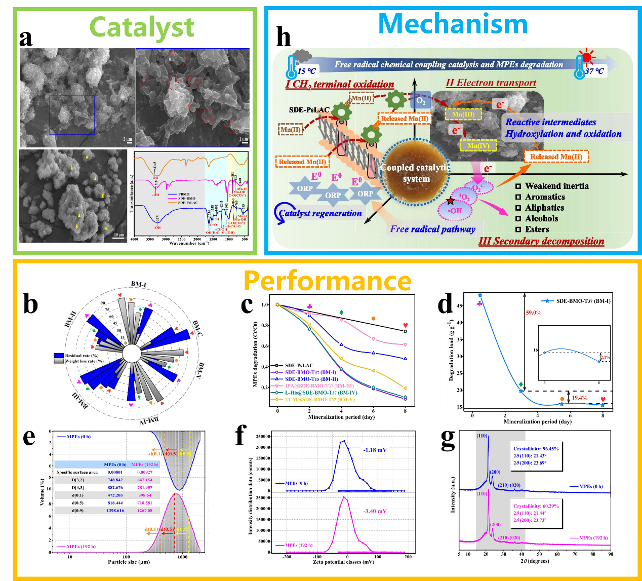
Fig. 24. (a) Morphology of the SDE-BMO catalyst. The performance of catalysts in the degradation of plastics BM series (b) and SDE-BMO series (c). (d) Change in degradation load (BMO amount loading per unit of MPEs substrate) during cultivation time of SDE-BMO-T37. (e) Comparison of MPE particle sizes before and after degradation. (f) Comparison of zeta potential values and distribution before and after degradation. (g) Comparison of XRD before and after degradation. (h) Proposed mechanism of MPEs removal by the SDE-BMO coupled system. Reprinted with permission from Ref. [264]. Copyright 2025, Elsevier.
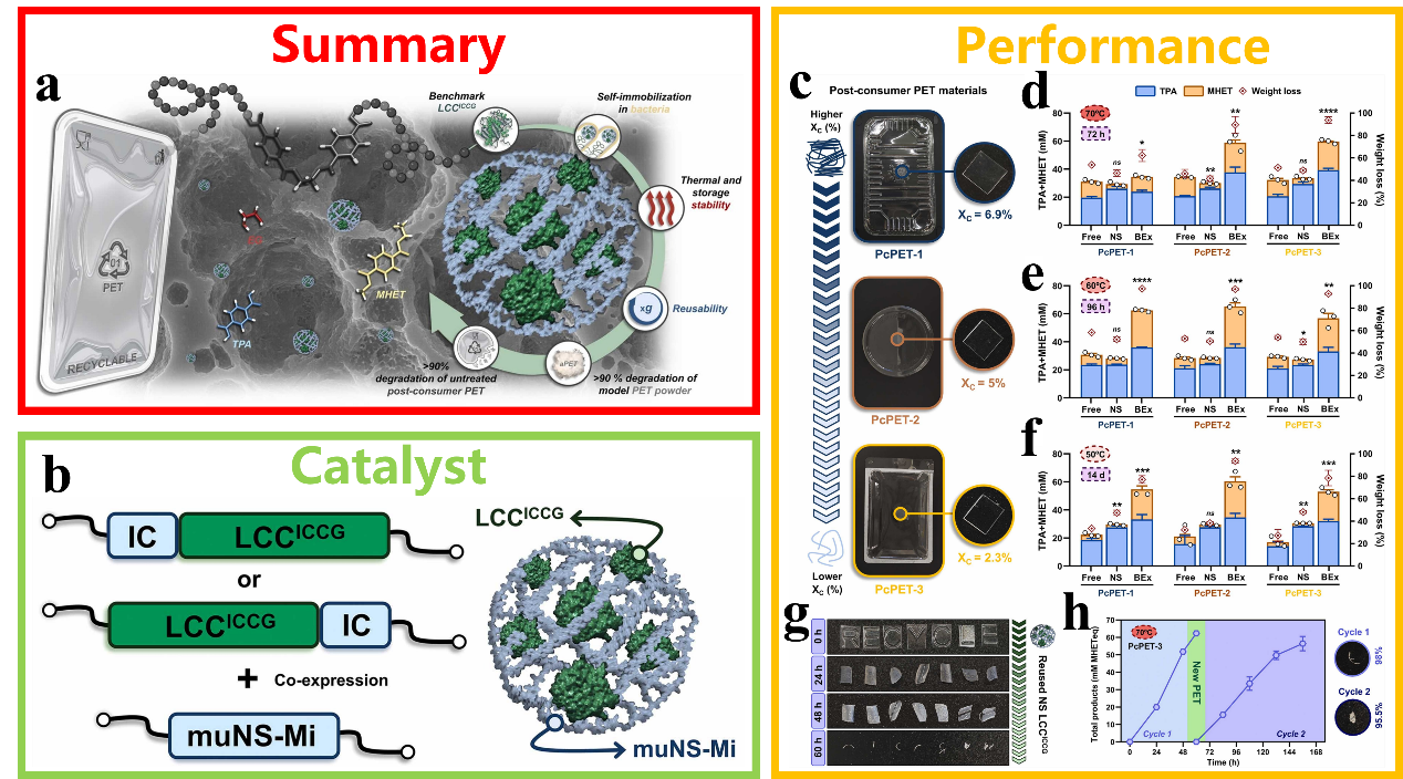
Fig. 25. (a) Schematic diagram of PET plastic conversion by LCCICCG hydrolase. (b) Schematic diagram of the synthesis of IC-tagged LCCICCG and enzyme-containing nanospheres. (c) Untreated post-consumer PET for degradation testing. (d‒f) Comparison of PET hydrolysis activity under different conditions. (g) The degradation performance of reused LCCICCG on PcPET-3 at 70 °C. (h) Performance of reused immobilized LCCICCG after two cycles at 70 °C. Reprinted with permission from Ref. [265]. Copyright 2025, Elsevier.
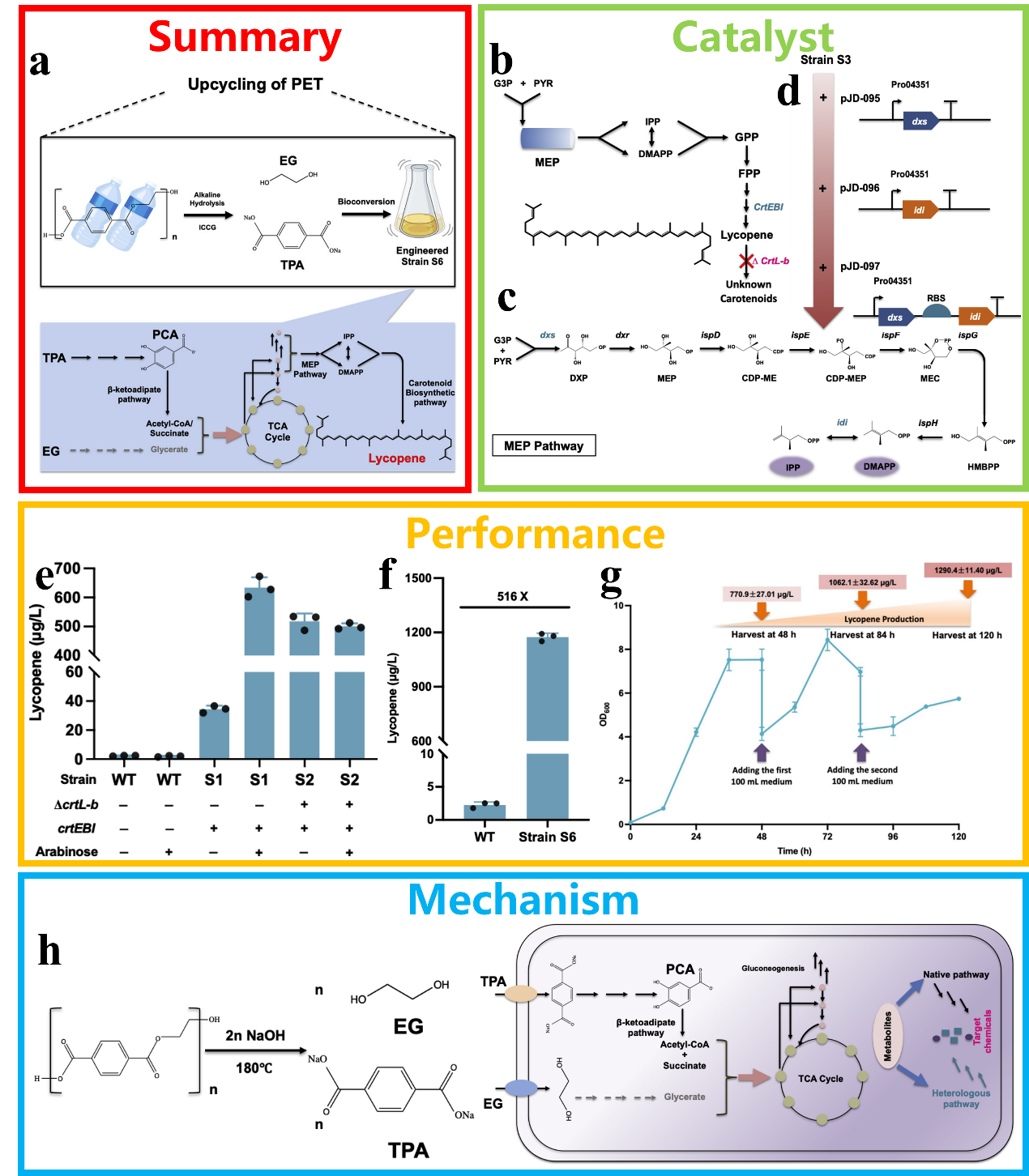
Fig. 26. (a) Schematic diagram of a microbial system converting PET into value-added chemicals. (b) Process flow diagram for the synthesis of lycopene via the modification of endogenous carotenoid-producing organisms. (c) Schematic of the endogenous MEP pathway. (d) Schematic overview of the overexpression of the key genes in the MEP pathway. (e) HPLC analysis of lycopene production in RPET and its derivative strains. (f) Performance of WT and strain S6 in the conversion of PET to lycopene. (g) Fed-batch fermentation in shake flasks for lycopene production using PET hydrolysate. (h) The mechanism by which PET hydrolysate is converted into lycopene on RPET. Reprinted with permission from Ref. [266]. Copyright 2023, Elsevier.

Fig. 27. (a) Schematic diagram of conformation selection in the biocatalytic degradation of plastics by PETase. (b) The overall structure of IsPETase (PDB ID: 6EQE). (c) Comparison of PETase activity across different substrate conformations and particle sizes. (d) Possible mechanisms underlying cross-substrate preference in the S238A mutant. Reprinted with permission from Ref. [267]. Copyright 2025, American Chemical Society.
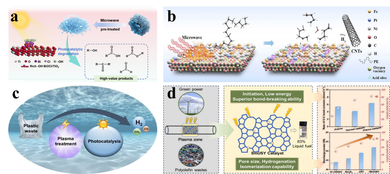
Fig. 28. (a) Microwave treatment combined with photocatalytic degradation of HDPE plastic. Reprinted with permission from Ref. [275]. Copyright 2025, Elsevier. (b) Microwave-assisted thermocatalytic conversion of LDPE to CNTs on a Pt-promoted Fe/Ni bimetallic catalyst. Reprinted with permission from Ref. [278]. Copyright 2026, Elsevier. (c) Photocatalytic conversion of plasma-treated PE on Pt/TiO2. Reprinted with permission from Ref. [279]. Copyright 2023, John Wiley and Sons. (d) Plasma-catalysed conversion of PE into fuel over Sm/USY. Reprinted with permission from Ref. [280]. Copyright 2026, Elsevier.

Fig. 29. (a) Schematic diagram of the photothermal degradation of plastics in an air-plastic-catalyst system. Reprinted with permission from Ref. [291]. Copyright 2024, John Wiley and Sons. (b) Schematic diagram of photothermal catalytic conversion of PE to propionic acid. Reprinted with permission from Ref. [292]. Copyright 2025, American Chemical Society. (c) Photocatalysis converts PET and CO2 into high-value products. Reprinted with permission from Ref. [293]. Copyright 2025, Elsevier. (d) Enzyme-assisted photocatalytic conversion of polyester plastics into fuels and chemicals. Reprinted with permission from Ref. [294]. Copyright 2023, American Chemical Society. (e) Synergistic conversion of PE plastic into microbial lipids via catalytic pyrolysis and biotransformation. Reprinted with permission from Ref. [295]. Copyright 2023, Elsevier.
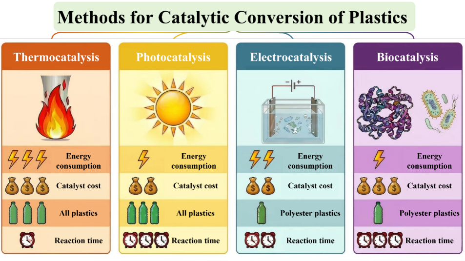
Fig. 30. A summary of various catalytic technologies used in the recycling of plastic waste.
|
| [1] | Sixian Li, Youyu Duan, Xinyuan Liang, Yuhan Li, Dieqing Zhang. Decoding the atomic architecture of photocatalytic active sites: From precise identification to rational design principles [J]. Chinese Journal of Catalysis, 2026, 83(4): 1-23. |
| [2] | Haoyi Wang, Yankai Zhang, Chunying Si, Yunbiao Qi, Quanxing Zhang, Wei Jiang. Dual-functional ionic liquid catalysts for efficient photooxidative upcycling of polystyrene to benzoic acid [J]. Chinese Journal of Catalysis, 2026, 83(4): 231-243. |
| [3] | Xuanrui Yang, Wenxuan Huang, Jianhua Shen, Chunzhong Li, Yihua Zhu. Electrocatalysts based on oxygen vacancy-induced frustrated Lewis pairs for selective electrooxidation of ethylene glycol to formic acid [J]. Chinese Journal of Catalysis, 2026, 91(12): 315-326. |
| [4] | Heng Zhang, Zeyu Zhang, Kunming Hou, Lin Jia, Yingxin Guo, Haorun Li, Mengbo Zou, Xianhu Sun, Shanghong Zeng. Pr(OH)3 nanorods on Cu generates asymmetric active sites through interplay and geometric deformation for CO2 electroreduction [J]. Chinese Journal of Catalysis, 2026, 90(11): 158-168. |
| [5] | Pengxiang Zhang, Jiawen Wang, Tianyu Yang, Ruizhe Wang, Ruofan Shen, Zhikun Peng, Yanyan Liu, Xianli Wu, Jianchun Jiang, Baojun Li. Unveiling complexities: Reviews on insights into the mechanism of oxygen evolution reaction [J]. Chinese Journal of Catalysis, 2025, 72(5): 48-83. |
| [6] | Qing Liu, Jin Shang, Zhendong Liu. Zeolites in the epoch of catalytic recycling plastic waste: Toward circular economy and sustainability [J]. Chinese Journal of Catalysis, 2025, 71(4): 54-69. |
| [7] | Lina Zhang, Guowei Liu, Xinyan Deng, Qiuye Li, Jianjun Yang. Atomically dispersed Ba sites as electron promoters to enhance the performance for photoreduction of CO2 [J]. Chinese Journal of Catalysis, 2025, 70(3): 341-352. |
| [8] | Lina Wang, Muhan Na, Ruofei Du, Xiujin Wang, Boyang Yu, Lan Yang, Hui Chen, Xiaoxin Zou. Ultrathin two-dimensional electrocatalysts: Structure-property relationships, mechanistic insights, and applications in water electrolysis [J]. Chinese Journal of Catalysis, 2025, 77(10): 4-19. |
| [9] | Chengguang Lang, Yantong Xu, Xiangdong Yao. Perfecting HER catalysts via defects: Recent advances and perspectives [J]. Chinese Journal of Catalysis, 2024, 64(9): 4-31. |
| [10] | Lujie Liu, Ben Liu, Yoshinao Nakagawa, Sibao Liu, Liang Wang, Mizuho Yabushita, Keiichi Tomishige. Recent progress on bimetallic catalysts for the production of fuels and chemicals from biomass and plastics by hydrodeoxygenation [J]. Chinese Journal of Catalysis, 2024, 62(7): 1-31. |
| [11] | Honghong Zhang, Zhiwei Wang, Lu Wei, Yuxi Liu, Hongxing Dai, Jiguang Deng. Recent progress on VOC pollution control via the catalytic method [J]. Chinese Journal of Catalysis, 2024, 61(6): 71-96. |
| [12] | Jingxiang Low, Chao Zhang, Ferdi Karadas, Yujie Xiong. Photocatalytic CO2 conversion: Beyond the earth [J]. Chinese Journal of Catalysis, 2023, 50(7): 1-5. |
| [13] | Yuannan Wang, Lina Wang, Kexin Zhang, Jingyao Xu, Qiannan Wu, Zhoubing Xie, Wei An, Xiao Liang, Xiaoxin Zou. Electrocatalytic water splitting over perovskite oxide catalysts [J]. Chinese Journal of Catalysis, 2023, 50(7): 109-125. |
| [14] | Zhipeng Huang, Yang Yang, Junju Mu, Genheng Li, Jianyu Han, Puning Ren, Jian Zhang, Nengchao Luo, Ke-Li Han, Feng Wang. Controlling the reactions of free radicals with metal-radical interaction [J]. Chinese Journal of Catalysis, 2023, 45(2): 120-131. |
| [15] | Yeqin Feng, Lin Qin, Junhao Zhang, Fangyu Fu, Huijie Li, Hua Xiang, Hongjin Lv. Wheel-shaped icosanuclear Cu-containing polyoxometalate catalyst: Mechanistic and stability studies on light-driven hydrogen generation [J]. Chinese Journal of Catalysis, 2022, 43(2): 442-450. |
| Viewed | ||||||
|
Full text |
|
|||||
|
Abstract |
|
|||||


