
催化学报 ›› 2026, Vol. 90: 27-51.DOI: 10.1016/S1872-2067(26)65188-1
周家璇a, 于耀东a, 韩佳倪a,b, 晁艳雪a, 赖建平a,*( ), 王磊a,*()
收稿日期:2026-01-05
接受日期:2026-03-16
出版日期:2026-11-18
发布日期:2026-09-09
通讯作者:
*电子信箱: jplai@qust.edu.cn (赖建平),基金资助:
Jiaxuan Zhoua, Yaodong Yua, Jiani Hana,b, Yanxue Chaoa, Jianping Laia,*(), Lei Wanga,*()
Received:2026-01-05
Accepted:2026-03-16
Online:2026-11-18
Published:2026-09-09
Contact:
*E-mail:jplai@qust.edu.cn(J. Lai),inorchemwl@126.com(L. Wang).
About author:Jianping Lai (Qingdao University of Science and Technology) received his PhD degree in 2017 from Changchun Institute of Applied Chemistry, Chinese Academy of Sciences. From 2017 to 2019, he did postdoctoral research at Peking University. He currently leads a research team focusing on advanced electrocatalytic materials for clean energy conversion and storage. He has coauthored more than 140 peer-reviewed papers.Supported by:摘要:
电催化质子加氢反应是能源转化、化学合成和环境修复等领域的核心反应过程. 传统上, 这类反应通常在酸性介质中进行, 以利用高浓度的H3O+作为质子供体, 实现高效的质子供给. 然而, 强酸性条件带来了严重的设备腐蚀、产物分离困难和大量废酸排放等环境与经济负担. 相比之下, 中性反应环境具有绿色、可持续且与生物体系兼容等显著优势, 但其极低的体相质子浓度导致了一系列严峻的挑战, 主要包括: 依赖水分子解离的质子供给动力学缓慢、热力学上更有利的析氢反应竞争激烈、气体反应物在中性水中的溶解度低导致传质受限, 以及多步反应路径复杂和电极界面微环境的动态不稳定. 因此, 系统解析中性介质中质子加氢反应的机理并发展高效的性能优化策略, 对于推动该技术的实际应用具有重要意义.
围绕上述核心挑战, 本文从三个尺度维度系统梳理了前沿性能优化策略. 在本征催化剂结构设计层面, 聚焦于通过电子结构与几何构型的精确调控, 协同提升水分子解离效率和活性氢物种的定向利用能力. 主要策略包括: 通过配位环境工程构筑单原子催化剂, 优化水活化能垒和中间体吸附能; 构建双位点协同催化体系, 利用氢溢流机制将产氢与加氢功能解耦, 抑制析氢反应; 利用缺陷工程构建不饱和配位中心, 增强水活化能力并稳定关键中间体. 在界面质子传输强化层面, 致力于构建高效的界面质子传输网络以克服传递瓶颈. 策略包括: 通过界面功能化引入官能团构建表面质子传导通路; 在有序框架中构筑仿生氢键网络, 实现快速定向质子输运; 引入光、热等外场, 重构质子-电子耦合的时空路径. 在反应工程与系统集成层面, 通过反应器与工艺流程的创新设计协同优化传质与反应路径. 核心策略包括: 构建气体扩散电极形成三相界面, 解除气态反应物的传质限制; 引入缓冲介质稳定界面pH并直接参与质子供给; 发展膜电极组件和串联催化技术, 精确管理界面离子传输并分解复杂反应网络, 提升目标产物选择性.
综上, 本文系统总结了中性介质中质子加氢反应的反应机理与核心挑战, 从本征催化剂设计、界面质子传输强化和反应工程与系统集成三个维度归纳了前沿优化策略及其内在关联. 本综述旨在加深领域研究者对中性介质质子加氢体系的系统性认知, 为进一步开发高效、稳定的中性质子氢化技术, 推动其在绿色化学合成与清洁能源转化领域的实际应用提供一定的参考和借鉴.
周家璇, 于耀东, 韩佳倪, 晁艳雪, 赖建平, 王磊. 中性介质中的质子加氢反应: 机理、挑战及性能提升策略[J]. 催化学报, 2026, 90: 27-51.
Jiaxuan Zhou, Yaodong Yu, Jiani Han, Yanxue Chao, Jianping Lai, Lei Wang. Proton hydrogenation reaction in neutral media: Mechanisms, challenges, and performance enhancement strategies[J]. Chinese Journal of Catalysis, 2026, 90: 27-51.
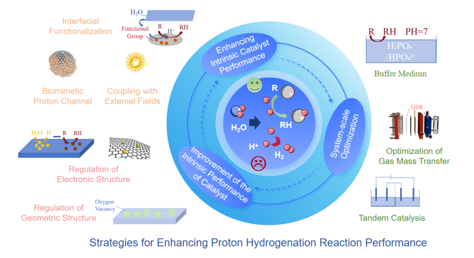
Fig. 1. A summary schematic diagram of the transformation of restrictive factors into constructive drivers for the performance enhancement of proton hydrogenation in neutral media and the corresponding multi-dimensional optimization strategies.
| Comparison dimension | Acidic media | Neutral media | Alkaline media |
|---|---|---|---|
| Primary proton source | H3O+ (high concentration) | H2O surface dissociation (virtually the sole source) | H₂O dissociation (buffered by OH-) |
| Proton concentration/M | 100-10-2 | ~10-7 (very low in bulk, no effective buffering) | 10-14-10-7 (very low in bulk, regulated by buffering at interface) |
| Proton supply mechanism | fast Volmer step (H3O+ + e- → H + H2O) | H2O dissociation as the primary pathway, slow kinetics | H2O dissociation and OH- buffering/consumption |
| Mass transport characteristics | fast proton transfer, moderate gas solubility | low gas solubility, significant mass transfer limitations; local pH prone to severe fluctuation | low gas solubility, OH- accumulation may affect interface stability |
| Key focus of catalyst design | fast proton transfer, moderate gas solubility | simultaneously promoting water splitting and suppressing HER, enhancing directed proton transfer, stabilizing dynamic interface | promoting water splitting, managing OH- accumulation, stabilizing interfacial environment |
| Major challenges | equipment corrosion, environmental burden, complex product separation | severely insufficient proton supply, intense HER competition, mass transfer limitations, dynamic instability of interfacial microenvironment | high initial energy barrier for water splitting, need to manage interfacial alkalinity |
Table 1 Characteristic comparison of proton hydrogenation reactions under different media environments.
| Comparison dimension | Acidic media | Neutral media | Alkaline media |
|---|---|---|---|
| Primary proton source | H3O+ (high concentration) | H2O surface dissociation (virtually the sole source) | H₂O dissociation (buffered by OH-) |
| Proton concentration/M | 100-10-2 | ~10-7 (very low in bulk, no effective buffering) | 10-14-10-7 (very low in bulk, regulated by buffering at interface) |
| Proton supply mechanism | fast Volmer step (H3O+ + e- → H + H2O) | H2O dissociation as the primary pathway, slow kinetics | H2O dissociation and OH- buffering/consumption |
| Mass transport characteristics | fast proton transfer, moderate gas solubility | low gas solubility, significant mass transfer limitations; local pH prone to severe fluctuation | low gas solubility, OH- accumulation may affect interface stability |
| Key focus of catalyst design | fast proton transfer, moderate gas solubility | simultaneously promoting water splitting and suppressing HER, enhancing directed proton transfer, stabilizing dynamic interface | promoting water splitting, managing OH- accumulation, stabilizing interfacial environment |
| Major challenges | equipment corrosion, environmental burden, complex product separation | severely insufficient proton supply, intense HER competition, mass transfer limitations, dynamic instability of interfacial microenvironment | high initial energy barrier for water splitting, need to manage interfacial alkalinity |
| Core challenge | Corresponding optimization strategies and primary mechanisms | Section |
|---|---|---|
| Limited proton supply | single-atom catalysts: Enable efficient water dissociation sites through precisely designed coordination environments, fundamentally enhancing proton generation efficiency. | 3.1, 3.2 |
| defect engineering: Create unsaturated coordination sites (e.g., O/S vacancies) to strengthen water molecule adsorption and activation. | ||
| interfacial functionalization: Introduce surface functional groups (e.g., -OH) to serve as proton relays, facilitating rapid interfacial proton transfer. | ||
| biomimetic proton transport channels: Construct directed and efficient proton conduction pathways (e.g., hydrogen-bond networks) within the material for rapid bulk proton supply. | ||
| Competitive reaction (HER) | single-atom catalysts: Finely tune the electronic structure (e.g., d-band center) of active sites via coordination engineering to optimize the hydrogen adsorption free energy (ΔG*H), steering it away from the optimal value for HER. | 3.1, 3.2 |
| defect engineering: Alter the local charge environment via defects to construct a proton fence, spatially or energetically hindering the HER pathway. | ||
| dual-site synergy: Spatially decouple proton generation (e.g., Fe sites) from substrate hydrogenation (e.g., Cu sites). The hydrogen spillover mechanism directs *H consumption, cutting off the feedstock supply for HER. | ||
| interfacial functionalization: Guide proton flow via surface functional groups to prioritize arrival at hydrogenation sites, reducing the accumulation of free *H. | ||
| Reagent mass transfer limitation | GDEs strategy: Establish a gas-liquid-solid three-phase interface, allowing gaseous reactants like CO₂ and N₂ to bypass the slow dissolution-diffusion process in the liquid phase and directly reach the catalyst surface, drastically increasing local concentration. | 3.3 |
| Complexity of reaction pathways | intrinsic catalyst design (e.g., single-atom/dual-site/defect engineering): Precisely modulate the adsorption strength for different reaction intermediates, breaking scaling relationships to steer the reaction along the desired pathway. | 3.1, 3.3 |
| intrinsic catalyst design (e.g., single-atom/dual-site/defect engineering): Precisely modulate the adsorption strength for different reaction intermediates, breaking scaling relationships to steer the reaction along the desired pathway. | ||
| system integration strategy (e.g., Tandem catalysis): Decompose multi-step complex reactions into sequential steps performed by different catalysts or in different reactors, simplifying control at each stage and enhancing final selectivity. | ||
| Dynamic instability of the interfacial microenvironment | introduction of buffer media: Utilize the proton buffering capacity of buffer pairs to promptly neutralize generated OH⁻, suppressing drastic local pH fluctuations. | 3.2, 3.3 |
| system integration strategy (e.g., Membrane electrode assembly): Employ ion-exchange membranes to precisely control ion transport, preventing OH- accumulation at the cathode interface and fundamentally stabilizing the microenvironment. | ||
| biomimetic proton transport channels: Establish efficient proton conduction networks to rapidly balance interfacial proton concentration, mitigating polarization effects caused by proton consumption. |
Table 2 Correspondence between core challenges and performance optimization strategies for proton hydrogenation in neutral media.
| Core challenge | Corresponding optimization strategies and primary mechanisms | Section |
|---|---|---|
| Limited proton supply | single-atom catalysts: Enable efficient water dissociation sites through precisely designed coordination environments, fundamentally enhancing proton generation efficiency. | 3.1, 3.2 |
| defect engineering: Create unsaturated coordination sites (e.g., O/S vacancies) to strengthen water molecule adsorption and activation. | ||
| interfacial functionalization: Introduce surface functional groups (e.g., -OH) to serve as proton relays, facilitating rapid interfacial proton transfer. | ||
| biomimetic proton transport channels: Construct directed and efficient proton conduction pathways (e.g., hydrogen-bond networks) within the material for rapid bulk proton supply. | ||
| Competitive reaction (HER) | single-atom catalysts: Finely tune the electronic structure (e.g., d-band center) of active sites via coordination engineering to optimize the hydrogen adsorption free energy (ΔG*H), steering it away from the optimal value for HER. | 3.1, 3.2 |
| defect engineering: Alter the local charge environment via defects to construct a proton fence, spatially or energetically hindering the HER pathway. | ||
| dual-site synergy: Spatially decouple proton generation (e.g., Fe sites) from substrate hydrogenation (e.g., Cu sites). The hydrogen spillover mechanism directs *H consumption, cutting off the feedstock supply for HER. | ||
| interfacial functionalization: Guide proton flow via surface functional groups to prioritize arrival at hydrogenation sites, reducing the accumulation of free *H. | ||
| Reagent mass transfer limitation | GDEs strategy: Establish a gas-liquid-solid three-phase interface, allowing gaseous reactants like CO₂ and N₂ to bypass the slow dissolution-diffusion process in the liquid phase and directly reach the catalyst surface, drastically increasing local concentration. | 3.3 |
| Complexity of reaction pathways | intrinsic catalyst design (e.g., single-atom/dual-site/defect engineering): Precisely modulate the adsorption strength for different reaction intermediates, breaking scaling relationships to steer the reaction along the desired pathway. | 3.1, 3.3 |
| intrinsic catalyst design (e.g., single-atom/dual-site/defect engineering): Precisely modulate the adsorption strength for different reaction intermediates, breaking scaling relationships to steer the reaction along the desired pathway. | ||
| system integration strategy (e.g., Tandem catalysis): Decompose multi-step complex reactions into sequential steps performed by different catalysts or in different reactors, simplifying control at each stage and enhancing final selectivity. | ||
| Dynamic instability of the interfacial microenvironment | introduction of buffer media: Utilize the proton buffering capacity of buffer pairs to promptly neutralize generated OH⁻, suppressing drastic local pH fluctuations. | 3.2, 3.3 |
| system integration strategy (e.g., Membrane electrode assembly): Employ ion-exchange membranes to precisely control ion transport, preventing OH- accumulation at the cathode interface and fundamentally stabilizing the microenvironment. | ||
| biomimetic proton transport channels: Establish efficient proton conduction networks to rapidly balance interfacial proton concentration, mitigating polarization effects caused by proton consumption. |
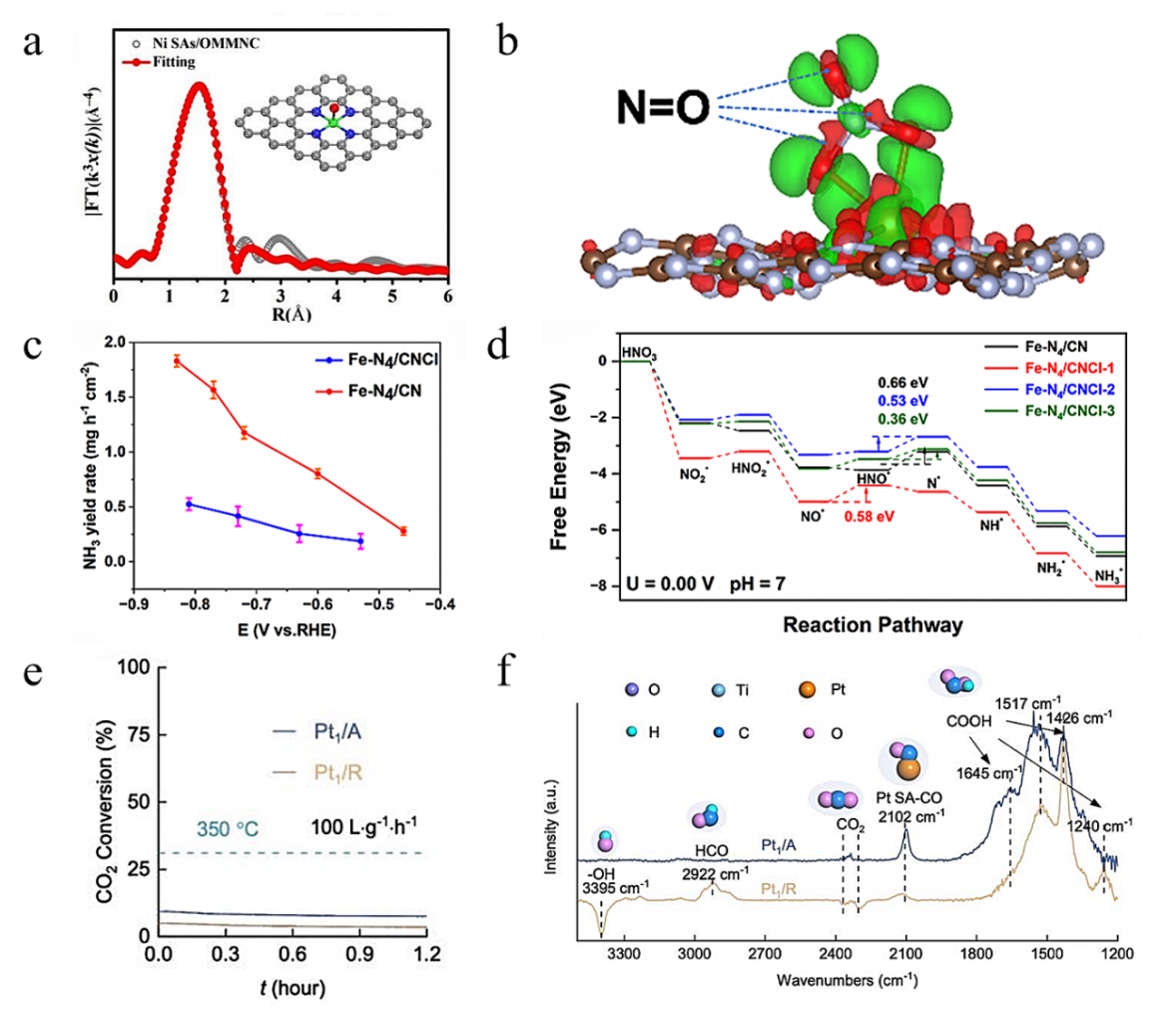
Fig. 2. (a) FT-EXAFS spectrum fitting of Ni SAs/OMMNC and the optimized configuration for Ni in the inset (the green, blue, red and gray spheres represent Ni, N,O and C atoms). Reprinted with permission from Ref. [67]. Copyright 2022, RSC Publishing. (b) Differential charge density of NO3- adsorbed on FeSAs/g-C3N4. Reprinted with permission from Ref. [68]. Copyright 2022, Elsevier. (c) Comparison of the NH3 yield rates (mg h−1 cm−2) of Fe-N4/CNCl and Fe-N4/CN catalysts. (d) Density functional theory calculations of reaction pathways for the NO3RR on Fe-N4 sites of Fe-N4/CN, Fe-N4/CNCl-1, Fe-N4/CN-2, and Fe-N4/CN-3. Reprinted with permission from Ref. [69]. Copyright 2025, American Chemical Society. (e) CO2 conversion at 350 °C. Reaction conditions: CO2:H2 = 1:4, weight hourly space velocity = 100 L g−1 h−1. (f) In-situ diffuse reflectance infrared Fourier transform spectroscopy over 30 min of TOS at 350 °C. Non situ and in-situ XPS spectra over 30 min of TOS at 350 °C. Reprinted with permission from Ref. [70]. Copyright 2025, Elsevier.
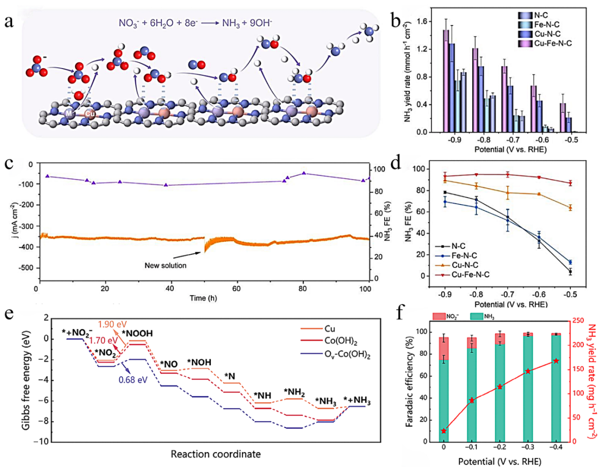
Fig. 3. (a) Conceptual diagram of the Cu-M-N-C structure to promote NO3RR activity. (b) NH3 yield rate of ammonia yield with electrolysis time for N-C, Cu-N-C, Fe-N-C, and Cu-Fe-NC. (c) Long-term NO3RR electrolysis and corresponding FE of NH3 for Cu-Fe-N-C. (d) The NH3 FE of ammonia yield with electrolysis time for N-C, Cu-N-C, Fe-N-C, and Cu-Fe-N-C. Reprinted with permission from Ref. [72]. Copyright 2024, RSC Publishing. (e) Free energy diagram of NO2RR. (f) NH3 yield rate and corresponding FE of NH3 for Ov-Co(OH)2/Cu at different electrode potentials. Reprinted with permission from Ref. [74]. Copyright 2025, John Wiley and Sons.
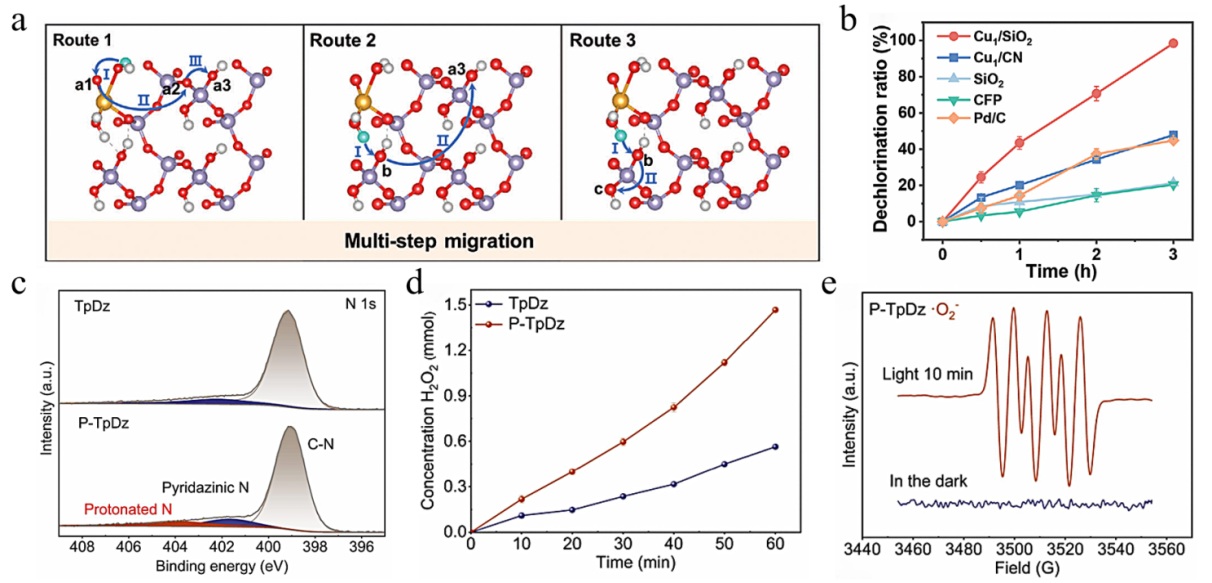
Fig. 4. (a) Possible migration routes of hydrogen spillover process for Cu1/SiO2 with surface hydroxyls. The yellow ball, purple ball, red ball, white ball, and cyan ball represent Cu, Si, O, H, and H*, respectively. (b) Corresponding CAP dechlorination ratio of CAP on various catalysts after 3 h electrolysis at −1.0 V vs. Ag/AgCl. Reprinted with permission from Ref. [78]. Copyright 2025, John Wiley and Sons. (c) XPS N 1s spectra of TpDz and P-TpDz. (d) Temporal H2O2 generation over TpDz and P-TpDz. (e) Electron spin resonance of O2−. Reprinted with permission from Ref. [79]. Copyright 2025, American Chemical Society.
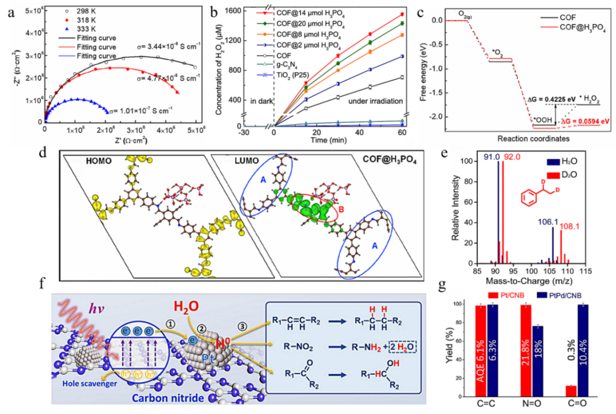
Fig. 5. (a) Nyquist plots for COF@H3PO4 at different temperatures. (b) Photocatalytic performance of H2O2 production using visible light for different catalysts (10 mg catalyst in 20 mL pure water, λ > 420 nm Xe lamp). (c) Free energy diagram for the two-electron ORR on the COF and COF@H3PO4. (d) The band charge density distributions of the HOMO and LUMO of COF@H3PO4 with an isovalue of 0.0004 e Å-3; the yellow and green colors represent the charge density distribution with and without electron occupation. Reprinted with permission from Ref. [80]. Copyright 2024, American Chemical Society. (e) Mass spectrometry spectra of the hydrogenation product (ethylbenzene) from using H2O or D2O. (f) Schematic illustration of the PWDTH process over the Pt/CN catalyst. Step 1: CN is light excited with the generated electrons transferring to the loaded Pt nanoparticles and holes being captured by scavenger (triethanolamine). Step 2: H2O is reduced to hydrogen (H0) over the Pt nanoparticles. Step 3: Organic molecules containing unsaturated double bonds (C=C, N=O and C=O) are in-situ hydrogenized at the Pt sites. (g) The yield and Apparent Quantum Efficiency (on columns) of the hydrogenation of styrene (C=C), nitrobenzene (N=O) and benzaldehyde (C=O) catalyzed by Pt/CNB and PtPd/CNB; light source: 380 nm LED, 20 mW cm-2. Reprinted with permission from Ref. [82]. Copyright 2020, American Chemical Society.
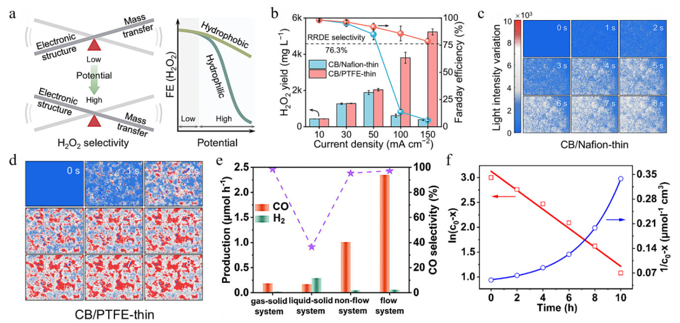
Fig. 6. (a) Schematic of species transfer governing H2O2 selectivity at the electrode scale. Red and white spheres represent oxygen and hydrogen, respectively. (b) H2O2 production performance of carbon black (CB)/Nafon-thin and CB/PTFE-thin at different current densities in 1 h. Mapping of surface absorbed light intensity (representing OH− concentration) as a function of electrolysis time for hydrophilic CB/Nafion-thin (c) and hydrophobic CB/PTFE-thin (d) at 100 m Acm−2. Reprinted with permission from Ref. [87]. Copyright 2024, Springer Nature. (e) Photocatalytic CO2RR activity and selectivity of Co-NGO under different reaction systems. (f) Plot of ln(c0 - x) and 1/c0 - x vs. time in non-flow system. Reprinted with permission from Ref. [89]. Copyright 2025, John Wiley and Sons.
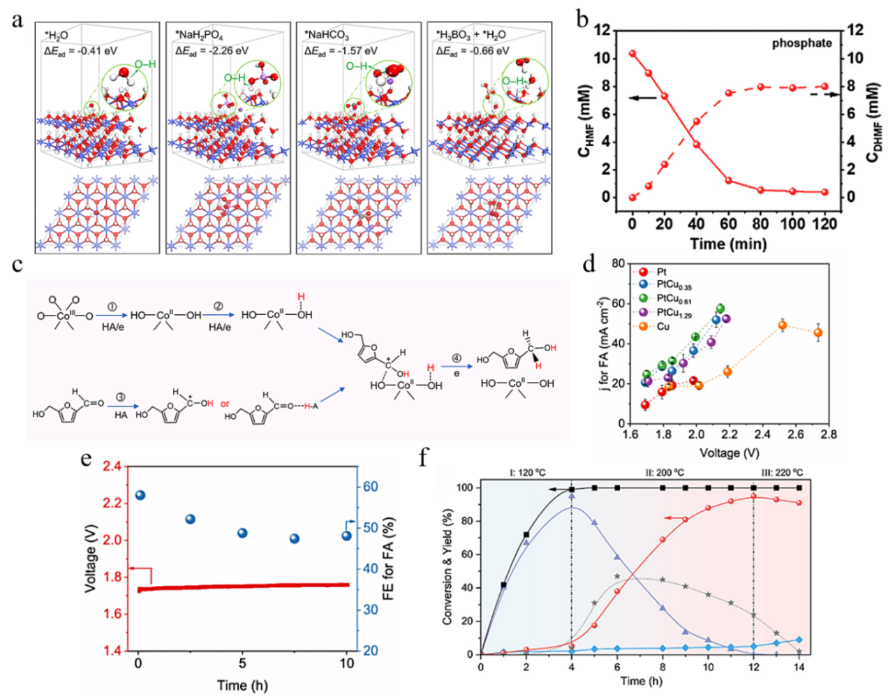
Fig. 7. (a) Energy-minimized configurations of different proton donors (H2O, NaH2PO4, NaHCO3, and H3BO3 + H2O) adsorption on the (001) surface of Co(OH)2. The ΔEad is the adsorption energy of the proton donors on Co(OH)2. Isosurfaces are 0.03 eV Å-3. (b) Concentration changes of HMF and DHMF in 0.1 mol L-1 phosphate during the chronoamperometry test at 1.2 V vs. Ag/AgCl. (c) The proposed reaction pathway in the real condition of the buffer-promoting electrocatalytic hydrogenation (ECH) process. Reprinted with permission from Ref. [90]. Copyright 2023, Elsevier. (d) Voltage-dependent current density for FA production of the Pt, PtCu0.35, PtCu0.61, PtCu1.29 and Cu electrodes in the MEA systems. (e) Cell voltage profile for the PtCu0.61 MEA system operative at 50 mA cm−2 for 10 h. Reprinted with permission from Ref. [92]. Copyright 2024, American Chemical Society. (f) Reaction profile of PET conversion over dual catalysts of Pd/r-GO and og-CuZn in temperature-programed mode. Reaction conditions: 100 mg PET, 50 mg og-CuZn and 50 mg of Pd/r-GO, 5 mL 1,4dioxane, 120 °C for 4 h, 200 °C for 8 h and 220 °C for 2 h, 6 MPa H2. Reprinted with permission from Ref. [95]. Copyright 2024, John Wiley and Sons.
|
| [1] | 顾宇, 张淑嘉, 徐铭潞, 闫昊, 周铭昊, 王磊, 施慧. 甲烷的脱氢芳构化及其与丙烷共芳构化: 反应机理、催化剂设计、积碳和过程强化[J]. 催化学报, 2026, 84(5): 25-60. |
| [2] | 李沛坤, 吕井辉, 赵以勇, 吴汉, 张祥豪, 陆倩楠, Yizhi Xiang, Blaž Likozar, Matej Huš, Adriana Zaleska-Medynska, 李小年. 迈向高效选择性加氢: 单原子催化剂的作用[J]. 催化学报, 2026, 81(2): 69-96. |
| [3] | Mansurbek Urol ugli Abdullaev, Woosong Jeon, Yun Kang, Juhwan Noh, Jung Ho Shin, Hee-Joon Chun, Hyun Woo Kim, Yong Tae Kim. 基于机器学习和优化算法的数据驱动框架预测用于合成气制烯烃的氧化物-沸石基复合催化体系和反应条件[J]. 催化学报, 2025, 74(7): 211-227. |
| [4] | 张利利, 周震. 电合成增值化学品: 从实验室研究到工业应用的挑战[J]. 催化学报, 2025, 73(6): 1-7. |
| [5] | 张朋祥, 王佳雯, 杨天宇, 王瑞哲, 沈若凡, 彭智昆, 刘艳艳, 武现丽, 蒋剑春, 李保军. 揭示复杂性: 析氧反应机理研究进展[J]. 催化学报, 2025, 72(5): 48-83. |
| [6] | 贡立圆, 陶李, 王雷, 符显珠, 王双印. 高温质子交换膜燃料电池阴极抗磷酸中毒催化剂的研究进展[J]. 催化学报, 2025, 68(1): 155-176. |
| [7] | 黄子超, 杨婷惠, 张颖冰, 管超群, 桂文科, 况敏, 杨建平. 提高酸性CO2电解的选择性:阳离子效应和催化剂创新[J]. 催化学报, 2024, 63(8): 61-80. |
| [8] | 朱鸿睿, 徐慧民, 黄陈金, 张志杰, 詹麒尼, 帅婷玉, 李高仁. 光电催化析氧和CO2还原反应催化剂的研究进展[J]. 催化学报, 2024, 62(7): 53-107. |
| [9] | Dmitry Yu. Murzin. 多相催化与均相自由基反应在药物废物销毁中的协同作用: 展望[J]. 催化学报, 2024, 58(3): 7-14. |
| [10] | 蒋亚飞, 刘锦程, 许聪俏, 李隽, 肖海. 打破合成氨反应中线性标度关系的碗型活性位点设计: 来自LaRuSi及其同构电子化物的启示[J]. 催化学报, 2022, 43(8): 2183-2192. |
| [11] | Ernest Pahuyo Delmo, 王忆安, 王菁, 朱尚乾, 李铁怀, 秦雪苹, 田一博, 赵青蓝, Juhee Jang, 王一诺, 谷猛, 张莉莉, 邵敏华. 金属有机框架-离子液体混合催化剂用于电化学还原二氧化碳生成甲烷[J]. 催化学报, 2022, 43(7): 1687-1696. |
| [12] | 郑汉, 杨正午, 孔祥栋, 耿志刚, 曾杰. 二氧化碳电还原为甲烷的研究进展[J]. 催化学报, 2022, 43(7): 1634-1641. |
| [13] | 王梦茹, 王奕, 牟效玲, 林荣和, 丁云杰. 1,3-丁二烯选择性加氢催化剂的设计策略以及构效关系[J]. 催化学报, 2022, 43(4): 1017-1041. |
| [14] | 吴建祥, 杨雪晶, 龚鸣. 甘油电催化氧化的研究进展:催化剂、机理和应用[J]. 催化学报, 2022, 43(12): 2966-2986. |
| [15] | 陈霄, 石闯, 梁长海. 炔醇选择加氢催化剂研究进展[J]. 催化学报, 2021, 42(12): 2105-2121. |
| 阅读次数 | ||||||
|
全文 |
|
|||||
|
摘要 |
|
|||||


